×
INTELLIGENT WORK FORUMS
FOR ENGINEERING PROFESSIONALS

Contact US

Log In

Come Join Us!

Are you an
Engineering professional?
Join Eng-Tips Forums!
  • Talk With Other Members
  • Be Notified Of Responses
    To Your Posts
  • Keyword Search
  • One-Click Access To Your
    Favorite Forums
  • Automated Signatures
    On Your Posts
  • Best Of All, It's Free!

*Eng-Tips's functionality depends on members receiving e-mail. By joining you are opting in to receive e-mail.

Posting Guidelines

Promoting, selling, recruiting, coursework and thesis posting is forbidden.

Students Click Here

Motor contactor wiring check
3

Motor contactor wiring check

Motor contactor wiring check

(OP)
I am currently in the middle of learning electrical circuits for a project so go easy on me. I am wanting to make sure how I have our motor contactor laid out is correct and safe. If not, where can I improve?

Top L is incoming supply, 220V single phase that routes through a circuit breaker.

Circuit will have a STOP, START, and an Indicator Lamp.

Bottom R is outgoing voltage to a Servo motor drive with fusing before the drive.

CB and Fuse locations are specified in the servo drive manual.

No wire numbers yet, just indicating colors; Black (L1), White (Neutral)

RE: Motor contactor wiring check

You are missing a wire and a set of auxiliary contacts.
Wire numbers would help. You need a black wire.
Well, you nave wires connecting the "Emergency Stop Button", the "Power on Button" and the pilot light.
From that common point, run another wire to T3. (In place of an auxiliary contact.)
Run a jumper from L3 to A1.
Disclaimer:
This advice is based on the components being as described by the standard symbols.

Bill
--------------------
Ohm's law
Not just a good idea;
It's the LAW!

RE: Motor contactor wiring check

Hmmmm.. where to start..
First off you do not use the same 220 V to feed the servo as you use for the control circuit, they need to be separate with there own fuses.
Start with that and come back. winky smile

Best Regards A

“Logic will get you from A to Z; imagination will get you everywhere.“
Albert Einstein

RE: Motor contactor wiring check

In North America;
On a small motor, the circuit breaker may provide acceptable protection for short control circuits.
Different codes, Red.

Bill
--------------------
Ohm's law
Not just a good idea;
It's the LAW!

RE: Motor contactor wiring check

(OP)
@Waross, appreciate it. Is this better (blue wire for quick representation only)? I am learning that others in the past have not always set up things properly, so I want to learn myself this time.

The CB and fusing is from the manual, size and placement.

RE: Motor contactor wiring check

Okey smile
Coming from the industri world we would never make a stand alone funktion like that, so we always separats everything like power and control circuits.
With our standards that would not be a correct emergency stop function either.


Best Regards A

“Logic will get you from A to Z; imagination will get you everywhere.“
Albert Einstein

RE: Motor contactor wiring check

One thing if it is the drawing or the servo manual, L1 and L2 usually means 2 phases.
If it is powered 220 V AC it would have sade L1 ,N at least in Europe.


BR A

“Logic will get you from A to Z; imagination will get you everywhere.“
Albert Einstein

RE: Motor contactor wiring check

(OP)
@RedSnake, agree the L1 and L2 are confusing, but that is how the drive is labeled. Terminal T is used for 3 phase.

RE: Motor contactor wiring check

Well some servos can be driven with different power connection options both for control power L1, L2 and for power feed, R,S,T.
So one needs to read the manual properly to get it right, if the servo is programable there might be settings that needs to be made.

BR A

“Logic will get you from A to Z; imagination will get you everywhere.“
Albert Einstein

RE: Motor contactor wiring check

RedSnake: L1, N, L2 is standard North American numbering.
Don't feel bad. I found out the difference just in time when hooking up a European standby generator to a North American system.
The consequences could have been more exciting than finding out in a friendly discussion.

MScarn: I gave you a circuit based on the standard three wire motor control circuit that was old 60 years ago, and based on this disclaimer:

Quote:

This advice is based on the components being as described by the standard symbols.
Now you add non-standard information.
Check the manual, or RTFI.

Bill
--------------------
Ohm's law
Not just a good idea;
It's the LAW!

RE: Motor contactor wiring check

For Googlability, when waross says you're missing a wire and need an auxiliary contact that is in reference to "3 wire control". 3 wire is for push buttons and 2 wire is for switches.

RE: Motor contactor wiring check

waross I don't feel bad, no worry.
European standard L1 N = 220 VAC L1 L2 = 380 VAC and R, S, T incoming, U, V, W outgoing
I just saw 220 VAC and thought yes thumbsup2 I thought US only went by 120 VAC winky smile
I am very much for reading manuals so I guess I would have figured it out, if I had to.

Best Regards A

“Logic will get you from A to Z; imagination will get you everywhere.“
Albert Einstein

RE: Motor contactor wiring check

Old habits die hard.
In the 40's the standard voltages in North America were 110/220 Volts. In the 50's the voltages were raised at the rate of 1/2 Volts per year until 120/240 Volts was reached.
We had 5 years at 112/224 Volts, 5 years at 115/230 Volts, 5 years at 117/234 Volts and finally 120/240 Volts.
After generations of 110/220 Volts, the non-electrical public continued to refer to 220 Volts. This has been passed down to people who were born after 240 became the standard.
To make matters more confused, we see a lot of imported Asian equipment for the North American market labelled for 220 Volts.

Bill
--------------------
Ohm's law
Not just a good idea;
It's the LAW!

RE: Motor contactor wiring check

(OP)
Waross, what is non standard? Just wanting to learn. I understand now about using the L3 and T3 terminals as the auxiliary contacts.

Edit; I see I have a wire color mislabeled @ L1 (should be black, not white)

RE: Motor contactor wiring check

Quote (waross)

Old habits die hard.
True smile
I still think about European standard as 220 VAC, 3-phase 380 VAC but now it is actually 230 VAC, 3-phase 400V. lol
I am getting old. sad

/A

“Logic will get you from A to Z; imagination will get you everywhere.“
Albert Einstein

RE: Motor contactor wiring check

MScarn do you have a manual for this servo drive?

Best Regards A

“Logic will get you from A to Z; imagination will get you everywhere.“
Albert Einstein

RE: Motor contactor wiring check

I would expect L1 and L2 on the drive to be fed from the contactor, not directly from the breaker, unless;
What does the manual say?

Bill
--------------------
Ohm's law
Not just a good idea;
It's the LAW!

RE: Motor contactor wiring check

I have dealt with a lot of different kinds of servos drives and regardless of how old they are they usually have either functional inputs or are programable by a bus system.
Signals like enable, inhibit, backward, forward and run.
If this signals are going to be used the control power must be intact even if the power feed is off.
Depending on the drive or the function of the motor it can sometimes become a problem cutting off the control power since this functions can't be utilized.
But not knowing the servos functions or the motors function it is hard to tell.

Best Regards A

“Logic will get you from A to Z; imagination will get you everywhere.“
Albert Einstein

RE: Motor contactor wiring check

Thanks for the information, RedSnake.

Bill
--------------------
Ohm's law
Not just a good idea;
It's the LAW!

RE: Motor contactor wiring check

I'll start with something basic;
Why are you wanting a contactor ahead of a servo drive? Are you aware that it's not really a good idea to control a servo drive by turning power on and off to it every time? Servo drives, like all electronic drives, have what's called a "pre-charge" circuit inside that prevents the DC bus capacitors from damaging themselves when you first apply power. The pre-charge circuit puts a current limiting resistor in series with the DC feed to the caps for a second whenever you apply power, then shorts around it with a relay contact once the caps are fully charged. That resistor and relay have a limited lifespan, usually about 1,000 operations. So if used once in a blue moon, you may never see it fail in your lifetime. But if you cycle power once per day, you consume that lifespan in <3 years, if you do it 10 times per day, <1 year! As a general rule, having a "safety contactor" ahead of it is fine, because ostensibly that is only going to be operated in an emergency. But if thus is for general on-off control (meaning the "Panel Power On" button you show), I would feed that to the servo drive directly, leave the contactor tied only to the E-Stop only.

Your control circuit is incorrect by the way. The Power On pilot light will glow ever WITHOUT the Panel Power On button being depressed and the Aux contact (L3/T3) is not going to seal in around the Power On button. The way you have it will seal in around the E-Stop!

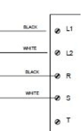
I'm also curious as to why your Servo drive has an L!, L2 input and an R,S,T input? I'm thinking these are the SAME input points, just labeled for different parts of the world; L1, L2 for North America where it would be more common to have 240V single phase, and R, S, T for the rest of the world where 240V 3 phase would be more common. A simple check would be to see if L1 and R are common to each other.


" We are all here on earth to help others; what on earth the others are here for I don't know." -- W. H. Auden

RE: Motor contactor wiring check

(OP)
@Jraef, I see now, the black wire should be on the other side of the power on button correct? Front side would bypass the button (like I had it).

RE: Motor contactor wiring check

Correct.


" We are all here on earth to help others; what on earth the others are here for I don't know." -- W. H. Auden

RE: Motor contactor wiring check

There are now a number of conflicting diagrams.
The wire to the auxiliary contacts should come from the jumper between the stop and the start buttons.
Good catch on the pilot light.Jeff. The pilot light wire should be from the other side of the start button.
With the original wiring the pilot light would indicate "Mains Present" NOT "Drive Power Energized".

Bill
--------------------
Ohm's law
Not just a good idea;
It's the LAW!

RE: Motor contactor wiring check

Yes you would need to add a auxiliary contact if it was 3 phases.
I guess the start button is resilient and that you are going to use the emergency stop as a stop button too?

In the last example, one problem I have is that the you have constant power on T3.
Usually both for safety reasons and when measuring when looking for faults you expect all incoming power feeds to be on the same side of a contactor or relay.
L1, L2, L3 or T1, T2 ,T3 in your example it is L1, L2, T3.


In the picture above.
The black part to T3 and the black part to the lamp, should be connected on the left side of the start button.
And the part between A1 and L3 must go away.
And then you have to have a part from the left side of the emergency button to L3 instead.

I am a bit sleeping so if I am wrong I am sure someone will correct me.

BR A

“Logic will get you from A to Z; imagination will get you everywhere.“
Albert Einstein

RE: Motor contactor wiring check

Try and get some sleep, my friend.
Only the lamp wire needs to be moved to the left of the start button.
No other changes, except.
Optionally the connections to L3 and T3 may be interchanged. The circuit will work the same but that will agree with the convention that constant power is on the top and switched power is on the bottom.

Bill
--------------------
Ohm's law
Not just a good idea;
It's the LAW!

RE: Motor contactor wiring check

Maybe I am too much of an esthete. winky smile

I still think this would be a "nice" solution.
Or am I still to sleeping ponder


Best Regards A

“Logic will get you from A to Z; imagination will get you everywhere.“
Albert Einstein

RE: Motor contactor wiring check

Since I like coloring. smile Red Hot, Blue Neutral

Power contactor off: coil deenergized > lamp off


Start button pushed > coil energized > contactor pulled > lamp on


Power contactor on: Start button released > coil energized over L3-T3 > contactor pulled > lamp on


Power contactor off: Energency button pushed > coil deenergized > contactor fallen > lamp off


Best Regards A

“Logic will get you from A to Z; imagination will get you everywhere.“
Albert Einstein

RE: Motor contactor wiring check

That will work, but I have a small critique.
The connection from the start button to T3 should go from T3 to A1.
Electrically equivalent.
BUT:
The length of wire; T3 to A1 is a few inches. Start to T3 may be a couple of inches or it may be considerably longer.
When I taught a hands on course on industrial controls to industrial electricians, part of the course was an awareness of how a seemingly insignificant change in the wiring diagram could affect the amount of wire needed. Consider a conveyor with a stop-start station at each end. Do you want to run three wires for the length of the conveyor or run four wires?
The other issue is terminal points. we try to run from terminal to terminal and avoid splicing of more than two wires.
The terminals on most control devices will accommodate two wires.
The pilot light is normally located with the push buttons. It is normally the second wire connected to the left side of the start button.
With the T3 wire connected to A1, no three way splices are needed and no terminal has more than two wires.
PS: I like the way that you have interchanged L3 and T3.
Bill
--------------------
Ohm's law
Not just a good idea;
It's the LAW!

RE: Motor contactor wiring check

(OP)
The visual is much appreciated RedSnake, really helps.

Waross, I see your point about the using the wire runs efficiently, and avoiding the 3 wire junction. T3>A1 solves both.

RE: Motor contactor wiring check

waross I am not sure if you are addressing me or witch "drawing you are referring to.

Best Regards A

“Logic will get you from A to Z; imagination will get you everywhere.“
Albert Einstein

RE: Motor contactor wiring check

Hi Anna. The last set of drawings showing a tee splice to feed the pilot light.

Bill
--------------------
Ohm's law
Not just a good idea;
It's the LAW!

RE: Motor contactor wiring check

Okey smile Just me being lacy not drawing properly.

You mean you prefer it like this. winky smile


Or maybe even like this smile


Or maybe this is better ponder


/A

RE: Motor contactor wiring check

Yes. The last circuit captures my intent.
When I was heavily involved in both teaching and on the job control circuits, all of the major North American control manufacturers published booklets of standard motor control diagrams.
I tried always to base my circuits on standard circuits.
This had an advantage of making trouble shooting much easier for less experienced electricians.
I remember working on a printing press with both AC and DC motors some of which were reversing.
It took a while.
The drawings were in a non standard (By North American usage) format, and...
The prints were in Italian.
It was a long afternoon.
My boss had started on the press.
He was an excellent trouble shooter.
When he called me for help I knew it was going to interesting and challenging.

Bill
--------------------
Ohm's law
Not just a good idea;
It's the LAW!

RE: Motor contactor wiring check

Well I have been trouble shooting in an korean nut checker machine only korean in the drawings found two faults.

We also have an Italien Press where someone hade managed to reorganize the ElCad project, so all the contacts for contactors and relays hade been moved around in number order.
Witch meant that there it should have been a NO it could be a NC.
Looking in the drawing i was not possible to reset the emergency stopp. lol
It took years to fix the drawing so it became as it should and it was in Italian, Frizioni Motori smile

/A

“Logic will get you from A to Z; imagination will get you everywhere.“
Albert Einstein

RE: Motor contactor wiring check

Our drawings always looks like this.


/A

“Logic will get you from A to Z; imagination will get you everywhere.“
Albert Einstein

Red Flag This Post

Please let us know here why this post is inappropriate. Reasons such as off-topic, duplicates, flames, illegal, vulgar, or students posting their homework.

Red Flag Submitted

Thank you for helping keep Eng-Tips Forums free from inappropriate posts.
The Eng-Tips staff will check this out and take appropriate action.

Reply To This Thread

Posting in the Eng-Tips forums is a member-only feature.

Click Here to join Eng-Tips and talk with other members! Already a Member? Login


Resources

Low-Volume Rapid Injection Molding With 3D Printed Molds
Learn methods and guidelines for using stereolithography (SLA) 3D printed molds in the injection molding process to lower costs and lead time. Discover how this hybrid manufacturing process enables on-demand mold fabrication to quickly produce small batches of thermoplastic parts. Download Now
Design for Additive Manufacturing (DfAM)
Examine how the principles of DfAM upend many of the long-standing rules around manufacturability - allowing engineers and designers to place a part’s function at the center of their design considerations. Download Now
Taking Control of Engineering Documents
This ebook covers tips for creating and managing workflows, security best practices and protection of intellectual property, Cloud vs. on-premise software solutions, CAD file management, compliance, and more. Download Now

Close Box

Join Eng-Tips® Today!

Join your peers on the Internet's largest technical engineering professional community.
It's easy to join and it's free.

Here's Why Members Love Eng-Tips Forums:

Register now while it's still free!

Already a member? Close this window and log in.

Join Us             Close