I'll start with something basic;
Why are you wanting a contactor ahead of a servo drive? Are you aware that it's not really a good idea to control a servo drive by turning power on and off to it every time? Servo drives, like all electronic drives, have what's called a "pre-charge" circuit inside that prevents the DC bus capacitors from damaging themselves when you first apply power. The pre-charge circuit puts a current limiting resistor in series with the DC feed to the caps for a second whenever you apply power, then shorts around it with a relay contact once the caps are fully charged. That resistor and relay have a limited lifespan, usually about 1,000 operations. So if used once in a blue moon, you may never see it fail in your lifetime. But if you cycle power once per day, you consume that lifespan in <3 years, if you do it 10 times per day, <1 year! As a general rule, having a "safety contactor" ahead of it is fine, because ostensibly that is only going to be operated in an emergency. But if thus is for general on-off control (meaning the "Panel Power On" button you show), I would feed that to the servo drive directly, leave the contactor tied only to the E-Stop only.
Your control circuit is incorrect by the way. The Power On pilot light will glow ever WITHOUT the Panel Power On button being depressed and the Aux contact (L3/T3) is not going to seal in around the Power On button. The way you have it will seal in around the E-Stop!
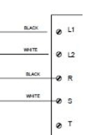
I'm also curious as to why your Servo drive has an L!, L2 input and an R,S,T input? I'm thinking these are the SAME input points, just labeled for different parts of the world; L1, L2 for North America where it would be more common to have 240V single phase, and R, S, T for the rest of the world where 240V 3 phase would be more common. A simple check would be to see if L1 and R are common to each other.
" We are all here on earth to help others; what on earth the others are here for I don't know." -- W. H. Auden


![[thumbsup2] [thumbsup2] [thumbsup2]](/data/assets/smilies/thumbsup2.gif) I thought US only went by 120 VAC ;-)
I thought US only went by 120 VAC ;-)![[lol] [lol] [lol]](/data/assets/smilies/lol.gif)