×
INTELLIGENT WORK FORUMS
FOR ENGINEERING PROFESSIONALS

Contact US

Log In

Come Join Us!

Are you an
Engineering professional?
Join Eng-Tips Forums!
  • Talk With Other Members
  • Be Notified Of Responses
    To Your Posts
  • Keyword Search
  • One-Click Access To Your
    Favorite Forums
  • Automated Signatures
    On Your Posts
  • Best Of All, It's Free!

*Eng-Tips's functionality depends on members receiving e-mail. By joining you are opting in to receive e-mail.

Posting Guidelines

Promoting, selling, recruiting, coursework and thesis posting is forbidden.

Students Click Here

Ripple Voltage

Ripple Voltage

Ripple Voltage

(OP)
Hi all,
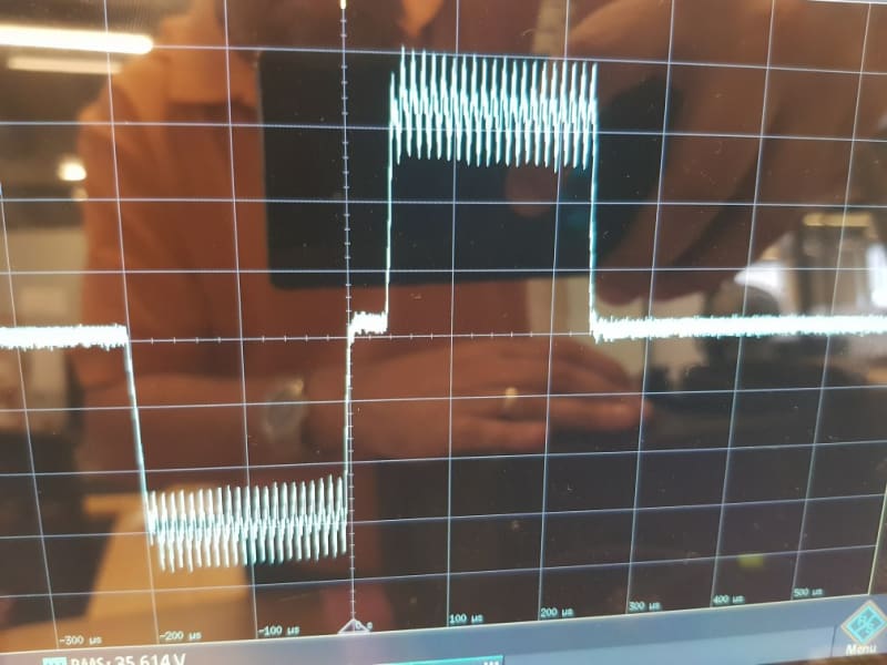
I have a tense circuit which outputs a bi phasic square signal at 12.5 hz.
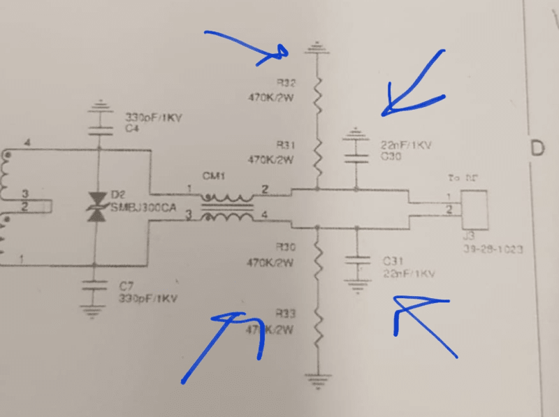
Apperantely it is creating a leakage current on the gnd line through the capcitors/resistors at the outputs which are connected to gnd.when u removed them, to keep the output floating, I receive a signal with ripple voltage on it, which explains why capacitors were used .is there another way to get rid of this ripple without the use if capacitors to gnd? Maybe dome kind of a common mode choke at the output? Any idea would be greatly appreciated.pics attached
Udi

RE: Ripple Voltage

If we had the schematic we might be able to come up with a non-capacitor solution...

Generally a capacitor is the solution. Often an optimized solution might require a different size to walk the line between too much leakage and a small enough ripple.

Typically a system would have the caps to its internal 0V bus and eventually you connect the 0V bus to your mains earth at a single point and most the leakage will circulate within your circuit and doesn't present an issue 'outside' the circuit as the leakage is with regards to the system's power supply.

Keith Cress
kcress - http://www.flaminsystems.com

RE: Ripple Voltage


How about connecting the caps and resistors to a common point instead of to ground?

Bill
--------------------
Ohm's law
Not just a good idea;
It's the LAW!

RE: Ripple Voltage

Well. There's already a common mode choke 'CM1'. Since this is coming directly via a transformer secondary I'm not seeing a way around caps. Why do you need to eliminate the ripple or the leakage?

Keith Cress
kcress - http://www.flaminsystems.com

RE: Ripple Voltage

(OP)
Hi Bill
I doubt that the resistors have any significance, however, how would you suggest connecting the caps?
Udi

RE: Ripple Voltage

My thinking is that if the ripple is line to line, then line to line capacitors and resistors may be effective without a ground connection. But, I will defer t your comments, Keith.

Bill
--------------------
Ohm's law
Not just a good idea;
It's the LAW!

RE: Ripple Voltage

(OP)
Hi Kieth,
I need to eliminate the leakage current as I cant pass the safety tests there's a leakage current coming from this circuit so I figured it had to do with either the resistors or caps.when I remove the caps I see this ripple, which is unwanted as well...

RE: Ripple Voltage

I don't fully understand the circuit.

If I was just focusing on the RC part. I could compute a time constant based on the r and c it would be tau = RC = 940E3 X 22e-9 = 0.020. (leaving out L from choke, not sure if it's valid or not).

tau = 0.020sec is short compared to T = 1/12hz = 0.080sec. It seems we'd like to increase tau in order to decrease ripple.

Increasing C is not an option since would increase leakage, but increasing R doesn't seem like it would hurt anything (?)

What if you increase resistor value ?

That should decrease ripple and decrease current draw. If it decreases ripple enough, you might be able to decrease C a bit to decrease current draw even more (at the cost of bringing back a bit of ripple).

Just a thought, I'm only focusing on the small R-C part of the circuit and don't understand the bigger circuit or the role of the common mode choke.

=====================================
(2B)+(2B)' ?

RE: Ripple Voltage

L/C ringing arising from leakage inductance of the choke and transformer ringing with your Y capacitors? May need R/C snubbers parallel to your Y capacitors.

RE: Ripple Voltage

(OP)
Hi
I hope the last diagram is more understandable.would appreciate your feedback whether snabbers would contribute to eliminate the ringing and what would be the recommended values .do I place them in parallel to each switch instead of the 0 ohm res?
Thanks

RE: Ripple Voltage

The latest schematic doesn't have a lot of resolution. It looks to be a push-pull setup, but then I seen high-side drivers and what appears to be a full-bridge MOSFET setup - somewhat unusual. So I won't comment on the primary.

As for my comments on the snubbers. Frequently "Y" capacitors, those caps from a AC output to chassis or ground, require snubbers to dampen ringing from the Y caps and parasitic circuit inductance. Now, I can't tell if the "ripple" of your scope picture is from parasitic L/C, or is actually related to something your circuit creats on the primary side of the transformer. Could also be your transformer primary needs a snubber.

As for Y snubbers - I'm not aware of a specific design technique to determine values. What I generally do is start by taking the Y capacitor value and splitting it 40/60 or 50/50. So for your 2.2nF I would might split it into a 1nF Y cap and a 1.2nF snubber cap. In series with the snubber cap I would place a resistor of 2 to 20 Ohms. I would then examine how much the ringing is dampened. I might then vary the snubber C and R values. Seeing how much snubbing action resulted gives me hints of the 'impedance' of the ringing source, and I might create a crude spice model to try R/C values.

Sometimes you don't see this ringing in a scope, and you only discover it when you go for emissions testing. In those cases the solution might be a snubber of 100pF and small R - all depending upon frequency.

RE: Ripple Voltage

(OP)
Hi,
Thanks for the elaborated answer.
However, as I explained in my initial thread those 22n caps connected to gnd are suspected to leak into gnd, so I removed them along with the 0.5M ohms resistors, and that's when I got the ringing at the output, so someone put them there to smoothe out the ringing.so I take it tha something is causing it to ring on the primary side?

Red Flag This Post

Please let us know here why this post is inappropriate. Reasons such as off-topic, duplicates, flames, illegal, vulgar, or students posting their homework.

Red Flag Submitted

Thank you for helping keep Eng-Tips Forums free from inappropriate posts.
The Eng-Tips staff will check this out and take appropriate action.

Reply To This Thread

Posting in the Eng-Tips forums is a member-only feature.

Click Here to join Eng-Tips and talk with other members! Already a Member? Login


Resources

Low-Volume Rapid Injection Molding With 3D Printed Molds
Learn methods and guidelines for using stereolithography (SLA) 3D printed molds in the injection molding process to lower costs and lead time. Discover how this hybrid manufacturing process enables on-demand mold fabrication to quickly produce small batches of thermoplastic parts. Download Now
Design for Additive Manufacturing (DfAM)
Examine how the principles of DfAM upend many of the long-standing rules around manufacturability - allowing engineers and designers to place a part’s function at the center of their design considerations. Download Now
Taking Control of Engineering Documents
This ebook covers tips for creating and managing workflows, security best practices and protection of intellectual property, Cloud vs. on-premise software solutions, CAD file management, compliance, and more. Download Now

Close Box

Join Eng-Tips® Today!

Join your peers on the Internet's largest technical engineering professional community.
It's easy to join and it's free.

Here's Why Members Love Eng-Tips Forums:

Register now while it's still free!

Already a member? Close this window and log in.

Join Us             Close