Tek-Tips is the largest IT community on the Internet today!

Members share and learn making Tek-Tips Forums the best source of peer-reviewed technical information on the Internet!

  • Congratulations MintJulep on being selected by the Eng-Tips community for having the most helpful posts in the forums last week. Way to Go!

STEEL CONNECTION HELP!

Status
Not open for further replies.

NAFTALI-HAKOHEN

Civil/Environmental
Joined
Apr 8, 2021
Messages
27
Location
IL
hi wondering how much of width of triangular plate takes the compression load from beam above, in corbel style connection
im designing:
Screenshot_2021-04-13_133346_d8fzle.jpg


Screenshot_2021-04-13_133654_mdpfd7.jpg


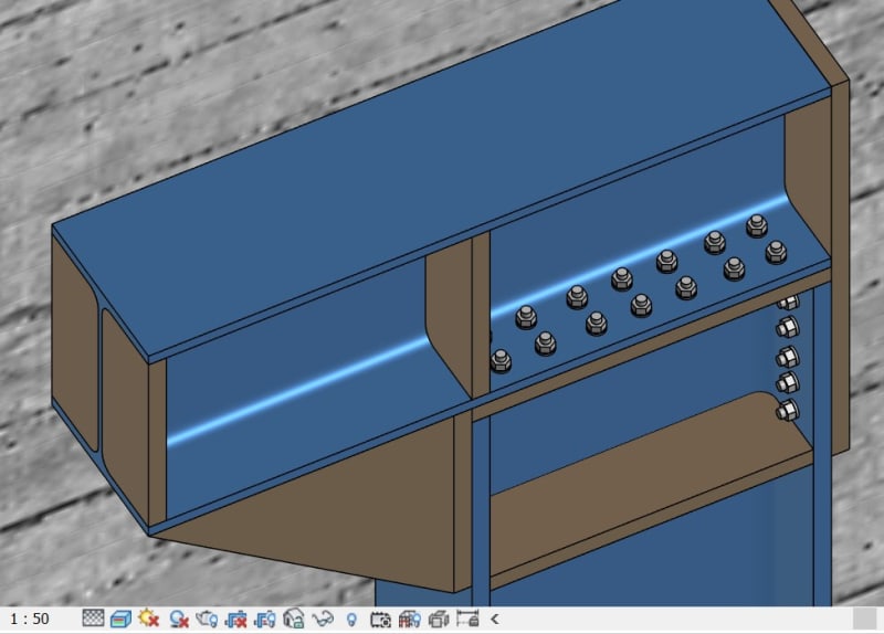
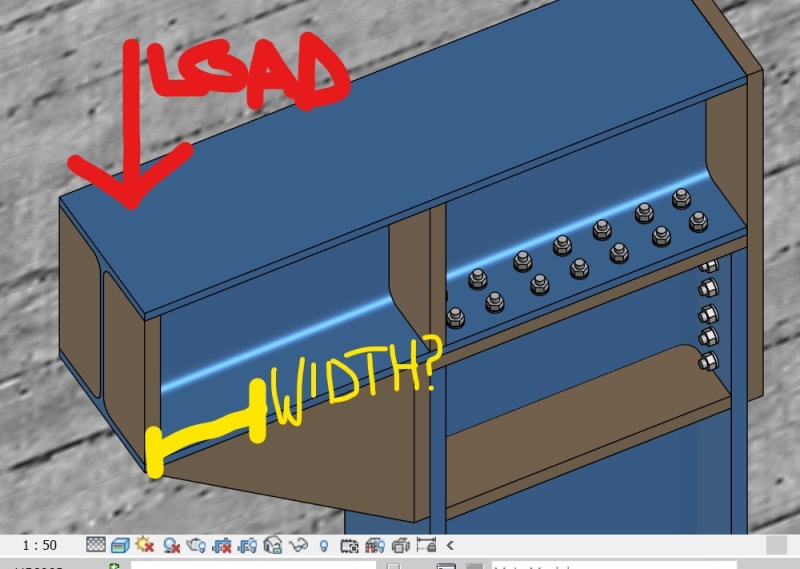
how wide is the design strip to take the compression?

and how do i calculate lateral compression length for a triangle like this- kind of laterally supported along its length?

thanks

naftali
 
Probably treat it similar to the bearing on a web format (10t+N) calculations.
 
A BS5950 book I have says 100mm is reasonable - and picks it out of thin air!
 
Why so many horizontal bolts? 28? seems a little overkill...

Rather than think climate change and the corona virus as science, think of it as the wrath of God. Feel any better?

-Dik
 
The closet similar thing I can think of is the stiffener plate in Bolted Extended End Plate Moment connections (see AISC Design Guide #4).

In that design guide examples, AISC does two checks on the stiffener:
1) Min thickness required for stiffener = thickness of beam web * (Fy_beam / Fy_stiffener)
2) b/t > 0.56*sqrt (E/Fy).... which is, I believe, based on the b/t slenderness limit for the flange of a wide flange under uniform compression.

If you follow those requirements, I believe the stiffener will not be subject to local buckling.
 
Status
Not open for further replies.

Part and Inventory Search

Sponsor

Back
Top