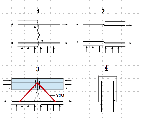
A contractor has provided construction joint at the location in Raft construction where the shear and moment is maximum at that location. So, any one does have any solution how can it be verified, if this construction joint is feasible or it needs rehabilitation?
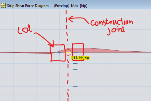
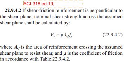
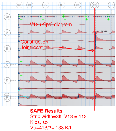
By considering shear friction design based on ACI-318-19 sect. 22.9, the bottom steel is not enough to resist the applied shear demand coming at the location of construction joint. The demand value of shear is shown in the figure below
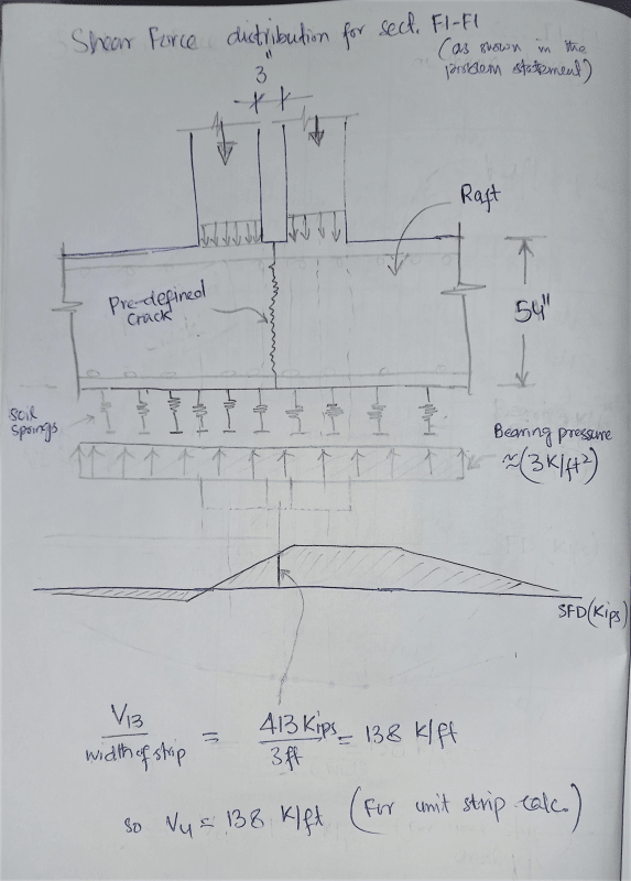
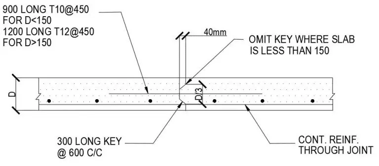
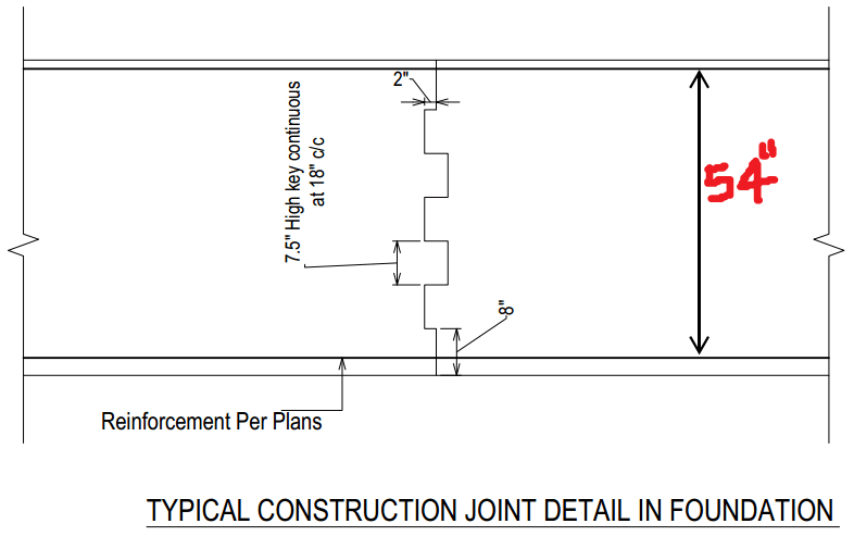
The design section detail is provided in the the section F1-F1
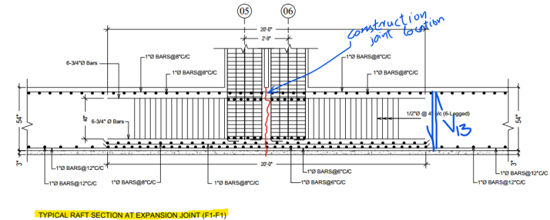
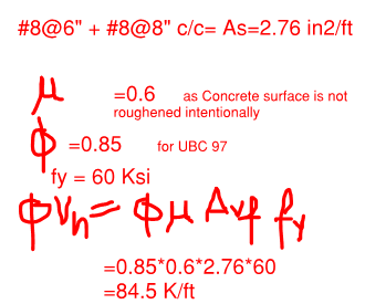
The Calculations are shown below, as the surface of the joint is not roughened intentionally rather it is smooth, so mu= 0.6,
By only considering the Bottom steel (in Tension), the shear friction capacity is not enough to resist the demand,
and i don't think that the top steel is contributing to shear friction.
 Malang_wazir
By considering shear friction design based on ACI-318-19 sect. 22.9, the bottom steel is not enough to resist the applied shear demand coming at the location of construction joint. The demand value of shear is shown in the figure below
The design section detail is provided in the the section F1-F1
The Calculations are shown below, as the surface of the joint is not roughened intentionally rather it is smooth, so mu= 0.6,
By only considering the Bottom steel (in Tension), the shear friction capacity is not enough to resist the demand,
and i don't think that the top steel is contributing to shear friction.
phi Vn < Vu not OK