Please allow me to continue the previous thread (Miami Pedestrian Bridge, Part XIV) as the prior is getting unwieldy.
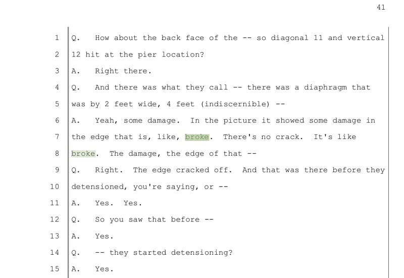
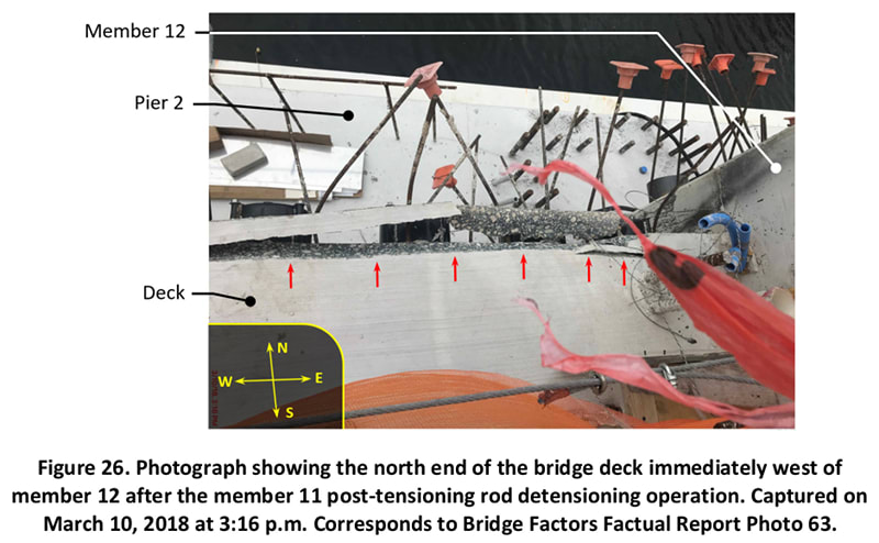
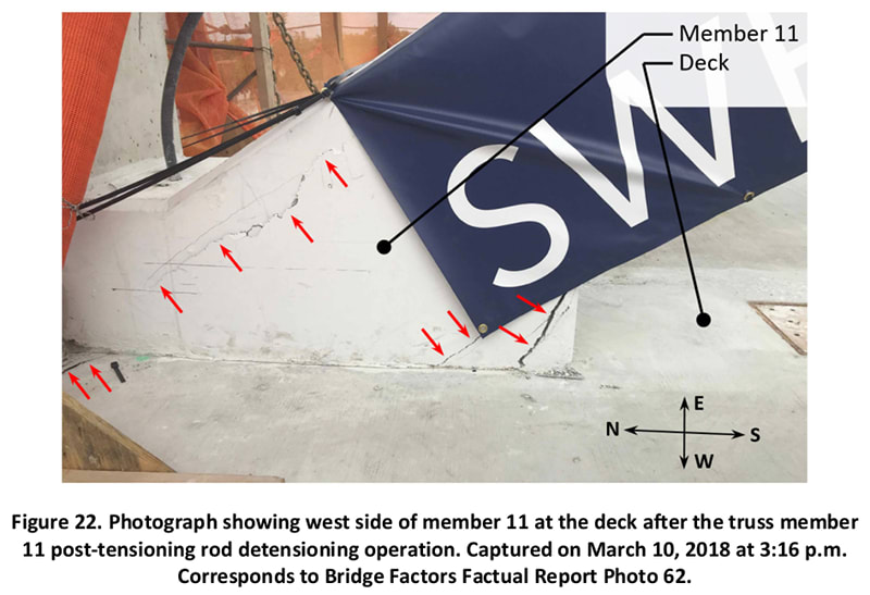
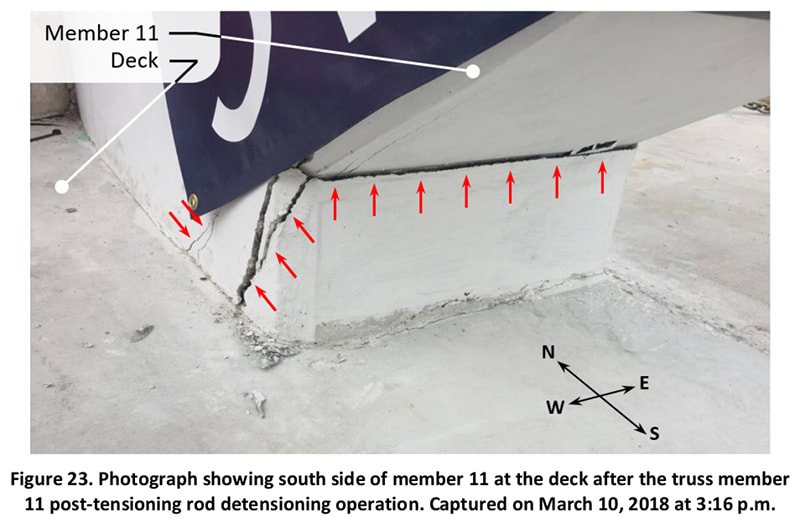
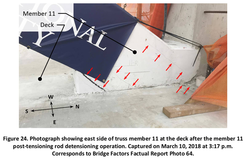
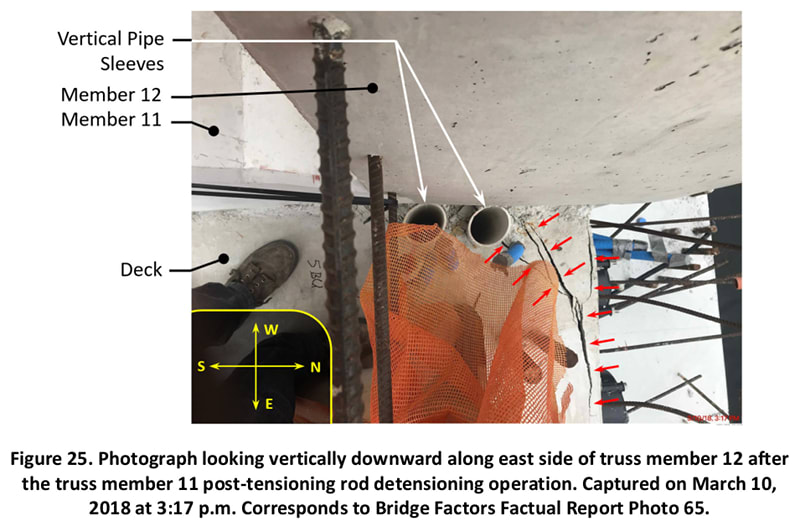
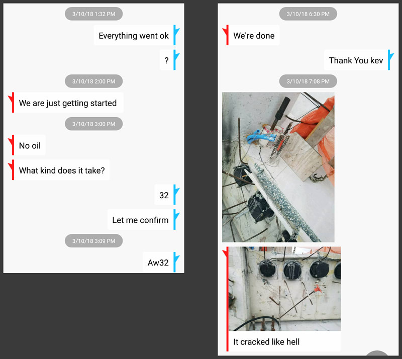
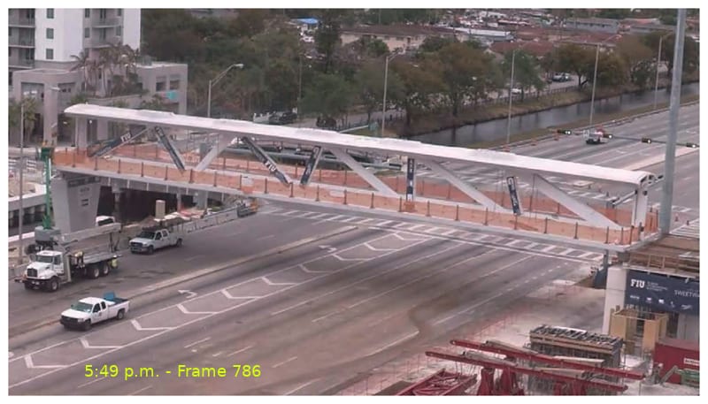
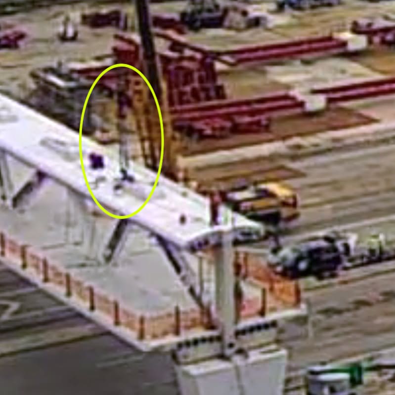
For those who have lost track of the discussion, my summary is that we have most recently moved into a discussion of the progression of nodal region deterioration of members 11, 12 and the deck as it pertains to the physical placement of the structure in its permanent location, then detensioning of PT rods in member 11, and then prior to retensioning of same. Epoxybot was able to connect the timeline of texts sent by Kevin Hanson inquiring of necessary supplies prior to detensioning with the timestamp on photos indicating significant deterioration prior to detensioning. I was reviewing documentation trying to narrow down on this timeline to confirm this critical detail with the implication that analysis contributed to the NTSB review has conflated events and attributed them to post-detensioning occurrences thus leading further analysis astray.
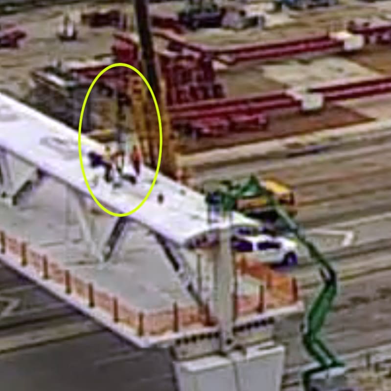
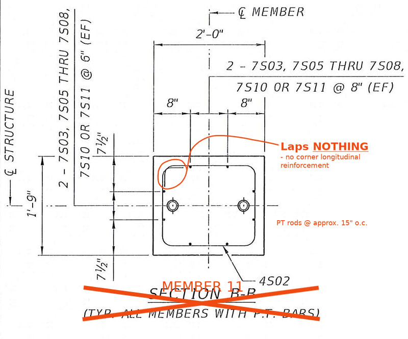
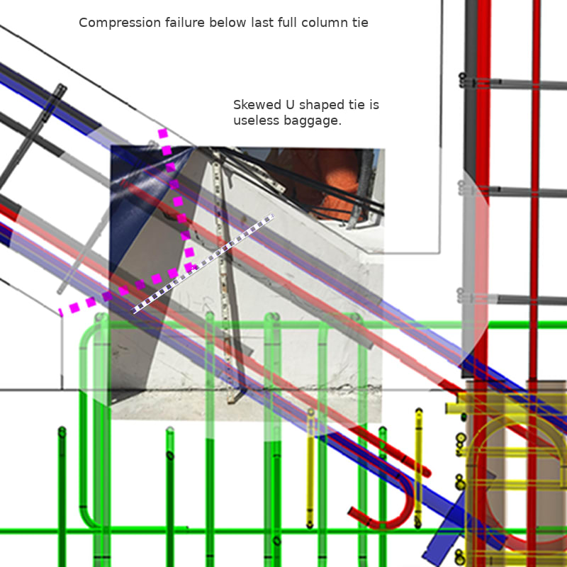
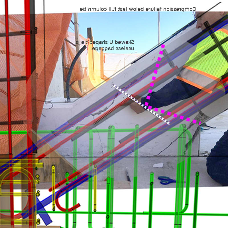
I have also posted what I consider evidence of compression failure of member 11 as the leading event of the collapse immediately after completion of retensioning PT rods in member 11. This includes questionable reinforcing design and deformation patterns in exposed rebar post-collapse.
To forward my own hypothesis, it is that two failure mechanisms were at play, one was the nodal region degeneration, and the second was the member 11 degeneration as it came into the nodal region. Although they played into each other, the weaker nodal region allowed the deck to detach from the node but the structure was able to rely on the connection of the diaphragm with the repurposed member 12 (i.e. a connection not including the deck). Meanwhile, the demand on the flawed member 11 grew and the structure collapsed when 11 failed just above the node.
P.S. With this new and more nuanced timeline, it allows the identification of three significant events to member 11:
For those who have lost track of the discussion, my summary is that we have most recently moved into a discussion of the progression of nodal region deterioration of members 11, 12 and the deck as it pertains to the physical placement of the structure in its permanent location, then detensioning of PT rods in member 11, and then prior to retensioning of same. Epoxybot was able to connect the timeline of texts sent by Kevin Hanson inquiring of necessary supplies prior to detensioning with the timestamp on photos indicating significant deterioration prior to detensioning. I was reviewing documentation trying to narrow down on this timeline to confirm this critical detail with the implication that analysis contributed to the NTSB review has conflated events and attributed them to post-detensioning occurrences thus leading further analysis astray.
I have also posted what I consider evidence of compression failure of member 11 as the leading event of the collapse immediately after completion of retensioning PT rods in member 11. This includes questionable reinforcing design and deformation patterns in exposed rebar post-collapse.
To forward my own hypothesis, it is that two failure mechanisms were at play, one was the nodal region degeneration, and the second was the member 11 degeneration as it came into the nodal region. Although they played into each other, the weaker nodal region allowed the deck to detach from the node but the structure was able to rely on the connection of the diaphragm with the repurposed member 12 (i.e. a connection not including the deck). Meanwhile, the demand on the flawed member 11 grew and the structure collapsed when 11 failed just above the node.
P.S. With this new and more nuanced timeline, it allows the identification of three significant events to member 11:
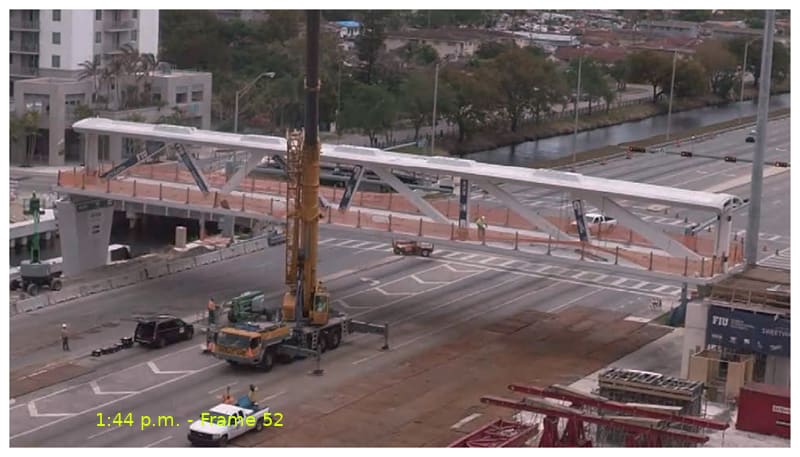
1 - Overloading upon removal of shoring followed by release when mounted on transporters,
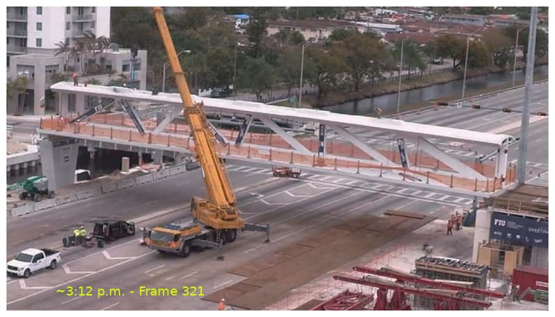
2 - Overloading upon setting on piers followed by release with detensioning,
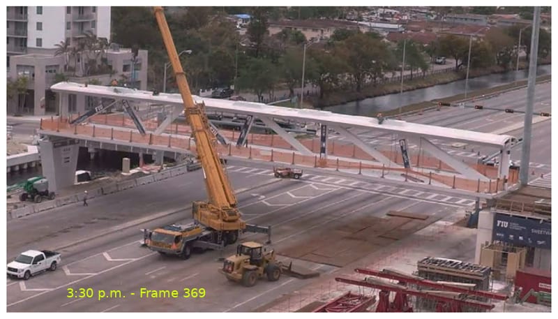
3 - Overloading upon retensioning of PT rods followed by collapse.
2 - Overloading upon setting on piers followed by release with detensioning,
3 - Overloading upon retensioning of PT rods followed by collapse.