×
INTELLIGENT WORK FORUMS
FOR ENGINEERING PROFESSIONALS

Contact US

Log In

Come Join Us!

Are you an
Engineering professional?
Join Eng-Tips Forums!
  • Talk With Other Members
  • Be Notified Of Responses
    To Your Posts
  • Keyword Search
  • One-Click Access To Your
    Favorite Forums
  • Automated Signatures
    On Your Posts
  • Best Of All, It's Free!

*Eng-Tips's functionality depends on members receiving e-mail. By joining you are opting in to receive e-mail.

Posting Guidelines

Promoting, selling, recruiting, coursework and thesis posting is forbidden.

Students Click Here

Force vs. Displacement in Creo Simulate

Force vs. Displacement in Creo Simulate

Force vs. Displacement in Creo Simulate

(OP)
In prosthetic foot development, there is a test called the ISO 10328 in which an Instron machine pushes on the bottom of a prosthetic foot (simulating walking) until a certain force is reached. The machine then returns a force vs. displacement graph which allows you to get an understanding of the prosthetic foot's spring properties. Usually you can see the force ramp up from zero to the max in the shape of a bell curve.

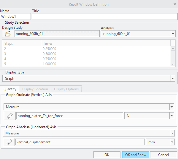
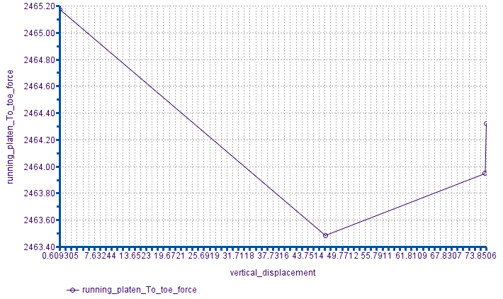
I need to replicate this graph in Creo Simulate to compare the FEA setup and the real-life prototype. However, when I use Measures I get this strange, nearly constant force plot with only four data points. The simulation doesn't operate the same as it would in real life: I think that instead of moving slowly into the prosthetic toe tip, the simulated machine rams into the simulated prosthetic toe tip trying to maintain constant force. This defeats the purpose of the simulation. The lack of data points is also a big issue. How do I fix this?


Red Flag This Post

Please let us know here why this post is inappropriate. Reasons such as off-topic, duplicates, flames, illegal, vulgar, or students posting their homework.

Red Flag Submitted

Thank you for helping keep Eng-Tips Forums free from inappropriate posts.
The Eng-Tips staff will check this out and take appropriate action.

Reply To This Thread

Posting in the Eng-Tips forums is a member-only feature.

Click Here to join Eng-Tips and talk with other members! Already a Member? Login


Resources

Low-Volume Rapid Injection Molding With 3D Printed Molds
Learn methods and guidelines for using stereolithography (SLA) 3D printed molds in the injection molding process to lower costs and lead time. Discover how this hybrid manufacturing process enables on-demand mold fabrication to quickly produce small batches of thermoplastic parts. Download Now
Design for Additive Manufacturing (DfAM)
Examine how the principles of DfAM upend many of the long-standing rules around manufacturability - allowing engineers and designers to place a part’s function at the center of their design considerations. Download Now
Taking Control of Engineering Documents
This ebook covers tips for creating and managing workflows, security best practices and protection of intellectual property, Cloud vs. on-premise software solutions, CAD file management, compliance, and more. Download Now

Close Box

Join Eng-Tips® Today!

Join your peers on the Internet's largest technical engineering professional community.
It's easy to join and it's free.

Here's Why Members Love Eng-Tips Forums:

Register now while it's still free!

Already a member? Close this window and log in.

Join Us             Close