×
INTELLIGENT WORK FORUMS
FOR ENGINEERING PROFESSIONALS

Log In

Come Join Us!

Are you an
Engineering professional?
Join Eng-Tips Forums!
  • Talk With Other Members
  • Be Notified Of Responses
    To Your Posts
  • Keyword Search
  • One-Click Access To Your
    Favorite Forums
  • Automated Signatures
    On Your Posts
  • Best Of All, It's Free!

*Eng-Tips's functionality depends on members receiving e-mail. By joining you are opting in to receive e-mail.

Posting Guidelines

Promoting, selling, recruiting, coursework and thesis posting is forbidden.

Students Click Here

MITC4 Plate Bending Elements
3

MITC4 Plate Bending Elements

MITC4 Plate Bending Elements

(OP)
I'm a full time engineer, but I've put together a sort of hobby computer program that does basic finite element analysis to help me learn how it works. I've been trying to add MITC4 elements for linear analysis (nothing too fancy) but I'm having some trouble. This is my first time creating isoparametric elements, so I'm learning.

I've modeled a 10' wide x 20' tall x 1' thick concrete rectangular wall panel (E = 3823 ksi, nu=0.17) fixed on on four sides with a uniform surface pressure of 250 psf. I've meshed it incredibly fine with 6"x6" rectangular plates.

The shear stresses my model is calculating are spot on with values published by Timoshenko in "Theory of Plates and Shells", but the bending stresses that are calculated are about 15% smaller. The displacement calculated at the center of the panel is also slightly larger (~10%) than Timoshenko predicts. I've plotted contours and the displaced shape and the shape of the bending moment, and they both look correct. Only the magnitudes appear to be slightly off. The excess deflection and low moments make me think my flexural stiffness is too low, but my stress-strain matrix [Cb] is the easiest matrix to calculate and I've checked it multiple times.

I've calculated my stresses as [Mx, My, Mxy] = [Cb][B][d], with [B] calculated at the 2x2 gauss integration points (+/-0.5773). I then extrapolated those stresses to the nodes using the shape functions. The extrapolation made very little difference with such a fine mesh, as the stress is nearly constant over the plate's area at locations of maximum moment. I don't think my extrapolation is the problem.

Any finite element geniuses out there with an idea what might be going on here? Do MITC4 bending elements require me to mesh even finer? My slow personal computer might blow up if I do. That seems like extremely poor convergence.
Replies continue below

Recommended for you

RE: MITC4 Plate Bending Elements

when you say "6"x6" rectangular plates" … how many elements through the thickness (1') ? minimum 3 for a bending field, the more the better.

btw, your mesh (800 elements) is not, IMHO, "incredibly fine".

you should do a single element check and compare your results with mainstream FEA codes. Then model structures … model simple ones first, ones you can hand calc the exact solution, like round plates.

another day in paradise, or is paradise one day closer ?

RE: MITC4 Plate Bending Elements

(OP)
These are MITC4 elements, so there's only 1 element through the thickness. They are 4 node quadrilateral bending elements. The reason I say 6"x6" is incredibly fine is because I've run this same problem through other software (STAAD) and gotten the results I expected.

RE: MITC4 Plate Bending Elements

still do a single element test. apply a moment causing bending across the thickness; how does the element deflect ?

another day in paradise, or is paradise one day closer ?

RE: MITC4 Plate Bending Elements

10'x 20'x 1' plate with pressure load on a fine grid model... sounds like a geometrically non-linear problem to me. how about doing a large disp non-linear analysis instead of a linear analysis and then calculating your responses??

RE: MITC4 Plate Bending Elements

(OP)
This is a concrete wall. Linear analysis is almost always used for this (see the Portland Cement Association's handbooks on concrete tank design). It's very arduous to model a composite anisotropic material such as cracked reinforced concrete nonlinearly. Usually the linear analysis is sufficient and the complex nonlinear effects are accounted for in the ACI design equations and effective stiffnesses codes prescribe.

RE: MITC4 Plate Bending Elements

okay I did a quick hand-calc using your panel dimensions/pressure-loading/properties and checked using Timoshenko and must admit the peak deflection values are very small compared against the panel thickness. So a linear analysis would suffice.

One thing that caught my eye in your explanation is you claim the FEA deflections results are higher than what Timoshenko predicts. This could be due to the fact that shell elements use transverse shear flexibility into their stiffness formulation whereas Timoshenko only considers the plate to be a bending panel. The presence of transverse shear flexibility (in addition to membrane and bending stiffness) makes the panel more flexible and thereby could increase the peak panel deflections. Is there a way you can ignore/turn-off the transverse shear flexibility option and run the panel just as a bending panel (meaning membrane plus bending stiffness only included)??

RE: MITC4 Plate Bending Elements

I have run the model as described in a commercial FEA package (Strand7), and compared with results from Roarke Table 11.4.8, which should be close to Timoshenko results.

I ran with a Poisson's Ratio of 0.17 and also 0.316, which is the default value given in Roarke. Results were (in SI units, sorry):

Max top face stress at mid-span
Stress, kPa FEA/Roarke
PR=.17 2.46E+03 0.993
PR=.316 2.45E+03 0.992

Deflection at mid-span
Deflection, mm FEA/Roarke
PR=.17 4.43E-04 1.067
PR=.316 4.11E-04 0.989

So stresses were very close to Roarke, regardless of the Poisson's Ratio, and deflections were only 7% greater with the low Poisson's Ratio.

I can only echo rb1957's suggestions.

Are you able to post the code for your plate element (or a link if there is an on-line source)?

Doug Jenkins
Interactive Design Services
http://newtonexcelbach.wordpress.com/

RE: MITC4 Plate Bending Elements

I finally got around to using MITC4 in ADINA. Modelled the OP's problem with his dimensions/properties/loading and compared the results with Timoshenko, and this is what I get:

dmax = max. deflection at the center of the panel (in inches)
Smax = max. bending stress at x=a/2, y=0 (using Timoshenko's co-ordinates) (in psi)

Timoshenko (dmax/Smax) = 0.00161/86.354
MITC4 (dmax/Smax) = 0.00176/73.473
MITC4/Timoshenko = +9%/-15%

MITC4 over-estimates the deflections by +9% and under-estimates the peak bending stress by -15% essentially matching the OP's claim in one of his earlier posts.

Now for the given dimensions, this plate has a L/t=20 making it borderline between thin and thick. It would be interesting to study the effects of transverse shear flexibility in such a scenario. The MITC4 documentation in ADINA does not give me the option to turn-off transverse shear effects (essentially moving between a thick to a thin plate modelling). I use NX/NASTRAN extensively. The CQUAD4 element present in NASTRAN gives me the option to easily switch b/w thin and thick plate modelling. So I tried to benchmark where the CQUAD4 element stands vis-a-vis standard MITC4 for the given problem. So here are the results:

Timoshenko (dmax/Smax) = 0.00161/86.354
MITC4 (dmax/Smax) = 0.00176/73.473
CQUAD4 (dmax/Smax) = 0.00181/73.413
MITC4/Timoshenko = +9%/-15%
CQUAD4/Timoshenko = +12%/-15%

The CQUAD4 is pretty much equivalent to the MITC4.

The above FEA results were obtained using transverse shear flexibility.

Timoshenko does not take into account the transverse shear effects in his solutions, so I re-ran the CQUAD4 FEA without the transverse shear effects and here are the results:

Timoshenko (dmax/Smax) = 0.00161/86.354
CQUAD4 (dmax/Smax) = 0.00161/73.531
CQUAD4/Timoshenko = 0%/-15%

As can be seen the deflection results perfectly match with that of FEA thereby showing the transverse shear flexibility of the plate has a role to play due to the L/t ratio. Not accounting for this is a limitation in closed form solution which the use of the FEA (in this case) gives the 'true' deflections.

So I would essentially go with the deflection results of the FEA in this case.

Now the underestimation of the stresses is purely due to the slow convergence of the 4-noded shell element. Both MITC4 and CQUAD4 has this issue. This only means that the current mesh size of 6 inches is not sufficient in the regions of high Mc/I stress and further refinement either in terms of a finer 4-noded shell mesh or switching to a 8-noded shell is required for convergence.

One useful tool CQUAD4 offers its users is the option of cubic-bending correction. This uses the grid point displacements and rotations to form a cubic equation for extrapolating the forces/stresses from centroids to the nodes. This works very well when using a coarse grid FEM to get internal forces/stresses of great accuracy.

So using the same mesh size of 6 inches and using this option of recovering nodal stresses on CQUAD4, I get:

Timoshenko (dmax/Smax) = 0.00161/86.354
CQUAD4 (dmax/Smax) = 0.00161/86.232
CQUAD4/Timoshenko = 0%/0%

So the stresses perfectly match. MITC4 does not use this option for force/stress extrapolation, so the only option is use a fine-grid model or a 8-noded shell model while dealing with MITC4 for stress convergence.


RE: MITC4 Plate Bending Elements

does "cubic correction" mean mid-side nodes ? (CQUAD8) ?

transverse shear effects are real (yes?), which Timoshenko neglected in his analysis. Has anyone analyzed a plate in bending including transverse shear effects ?

It would seem like we're (quite correctly) trying to reverse engineer Timoshenko's analysis in FEA, and then roll back there effects (to arrive at a better answer than Timoshenko … wot, better than Timoshenko??!!) ?

another day in paradise, or is paradise one day closer ?

RE: MITC4 Plate Bending Elements

I have now found the Timoshenko solution to this problem. For moments in the short span direction Roarke and Timoshenko agree exactly. Roarke doesn't give any results in the long span direction and I'll comment on the Timoshenko long span results later.

For deflections the Timoshenko solution include the effect of Poisson's Ratio, and the results with PR = 0.3 are very close to the Roarke results (about 0.1% difference). Although the main text in Roark says the rectangular plate results used a PR of 0.316, the start of the tables says 0.3, which based on the deflection values seems to be right.

I have also re-run my FEA with imperial units as in the original post, and with a PR of 0.17 and 0.30.

The results with PR = 0.17 agree almost exactly with nlgyro's last run, ie:
dmax = 1.608E-03 in
smax(edge) = 86.17 psi

smax(mid-span) = 42.63 (Timoshenko = 42.92)

With PR = 0.3 the deflection reduces to 1.510E-3 (Timoshenko = 1.512)

So the FEA results with cubic bending correction, and without shear deflections, agree almost exactly with Timoshenko results for deflection and moments/stresses in the short span direction (but see below for the other direction).

In summary, 4 node elements with dimensions as in the OP can give good results for bending, but only if the cubic bending correction is applied.

For the example given including shear deflections increased the maximum deflection by about 10%. I'd suggest that this is a bit academic for a concrete structure, since the combined effect of concrete cracking, shrinkage and creep may well be more than an order of magnitude greater.

Strand7 does not have an option for including shear deflections in the plate results, but using beam elements to model a fixed end span of 120 in, including shear deflections had the following results:
PR = 0.17: deflection increased by 11.2%
PR = 0.30: deflection increased by 12.5%
which is consistent with the increased deflections found with the MITC4 elements.

Regarding the moments and stresses in the long-span direction, I found a paper at:
https://www.nafems.org/downloads/nbr4.pdf
looking at stresses in a rectangular steel plate, simply supported along the short edges, comparing experimental results with Timoshenko and FEA results.

In summary, the paper found a significant difference between the stress ratio for mid-span in the X and Y directions as found from experiment and FEA (about 10) compared with Timoshenko (about 12). It suggests that this was probably a typo, but in my analysis I found a similar discrepancy for mid-span moments in the long direction between FEA and Timoshenko (FEA results were about 10% lower for PR = 0.17 and 15% higher for PR = 0.3). Since the Timoshenko table does not adjust any of the stress results for Poisson's Ratio, whereas the FEA results show a large difference in the long span stresses at midspan, this suggests the difference is a shortcoming in the theoretical values, rather than a typo.

Doug Jenkins
Interactive Design Services
http://newtonexcelbach.wordpress.com/

RE: MITC4 Plate Bending Elements

Quote (rb1957)

does "cubic correction" mean mid-side nodes ? (CQUAD8) ?

No, my analysis was with the Strand7 default 4 Node elements, and I assume nlgyro's last results were 4 node elements as well.

I don't know the details of how it works, but since it seems to give significantly better results I don't see the reason for not applying this correction

Doug Jenkins
Interactive Design Services
http://newtonexcelbach.wordpress.com/

RE: MITC4 Plate Bending Elements

I just tried the same model with 8 node plates:

Moments and stresses: no significant changes from 4 node, in either direction.
Deflections: increased to 1.801E-3 at mid-span.

Doug Jenkins
Interactive Design Services
http://newtonexcelbach.wordpress.com/

RE: MITC4 Plate Bending Elements

yes, I'd've been surprised if mid-side nodes helped on thru-thickness bending.

this must be quite a clever element compared to the CQUAD, which I thought performed badly for thru-thickness bending.

I think it'd still be worth running a single element test on this guy.

If we're tracking down a typo in Timoshenko, can't we (someone) redo the math to find the typo ?

another day in paradise, or is paradise one day closer ?

RE: MITC4 Plate Bending Elements

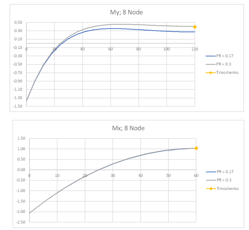
Some more background on the discrepancy between my results and Timoshenko for the long span moments:

Checking the Strand7 Theoretical Manual, it confirms that their 8 node plate element includes shear deflections, and the 4 node doesn't. Since the 4 node results are in good agreement with the Timoshenko deflections, and the 8 node results are in good agreement with nlgyro's results including shear deflection this suggests the Timoshenko numbers are correct for bending deflections only, ignoring shear strain.

For the bending moments, the Timoshenko table is based on a Poisson's Ratio of 0.3, and gives no adjustment for different values. Clearly (from symmetry) square plate would have equal bending moments in both directions, so there would be no adjustment in the moments for Poisson's Ratio. For a rectangle with side ratio of 2 though, the shape of the bending moment diagrams in each direction is very different:


Checking my results for Poisson's ratio = 0.3, the My (long span moment) is only about 3% greater than the Timoshenko value. I had previously compared the maximum moment, which occurs just past 1/4 span, rather than the mid-span value. This suggests that the Timoshenko My is a reasonable approximation for Poisson's ratio = 0.3, but the 0.17 My is significantly lower.

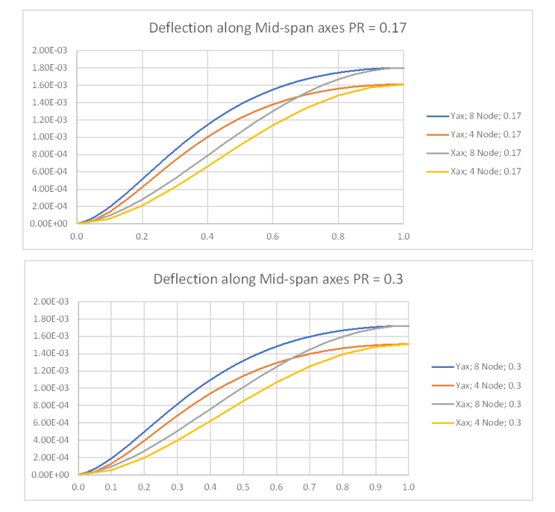
I have also plotted the midspan deflections along the x and y axes to a normalised scale, again showing very different shapes for the two directions, which suggests to me that there is no simple "exact" solution for rectangular plates:


In summary:

1) The proposed element size can give good results for both deflections and bending moments, but it needs a suitable plate element. The MITC4 element doesn't seem to give good results.

2) The Poisson's ratio has a significant effect on the mid-span moment in the long span direction, but only a small effect on the others (at least for the 2:1 shape examined).

3) Allowing for shear deflections has a significant effect, but for a concrete structure this will be minor compared with other approximations, such as the effects of concrete cracking, creep and shrinkage.

Doug Jenkins
Interactive Design Services
http://newtonexcelbach.wordpress.com/

RE: MITC4 Plate Bending Elements

Are you putting your code to github. I've been trying to get general solution to 4-node quadrilateral plate bending element together but can't get the link between the polynomials matrix to the [B] matrix. Have a closed form solution when the quadrilateral is a rectangle, but can't get it to work for general form.

RE: MITC4 Plate Bending Elements

(OP)
IDS you are brilliant. Thank you so much. You went above and beyond the call of duty! I wish I could give you 10 stars.

rscassar, I have posted my code to GitHub here: Quad3D.py This element still needs some polishing to finish it and make it user friendly, but it sounds from IDS's posts that my formulation is performing correctly so far. It sounds like it's not the formulation causing my problems, but the assumptions inherent to this element and Timoshenko's solutions.

Polynomial formulations work for rectangular elements, but I found for quadrilateral elements they are impossible to derive. I handed the matrix math to Sympy to crunch a solution and it choked. I tried again and left it solving overnight and it still choked. I've since learned that for this element you must abandon the polynomial displacement function formulation and use an isoparametric formulation and numerical integration at gauss points. That is where the [B] matrix comes from. It's actually easier than it sounds. You can look at my element and see how I did it. While I've used a lot of programs with plates, I've never derived them myself until now. I bought several books on FEA and spent the last few months trying to understand how this works. Authors in this field have a hard time dumbing this down enough for people like me, but I think I finally got it. Hopefully I've provided something that can be educational for you and others. Now that I know what's going on with this element, I'll soon have these MITC4 elements implemented as "Quad3D" elements in my program.

This program is a hobby I've been doing for quite some time in an effort to learn finite element analysis better and to learn Python. The overall project is called "PyNite" (a stupid play on words I thought was clever: Python + Finite) and can be found here here. If you're familiar with pip, you can install easily using "pip install PyNiteFEA". It works well for 3D frame structures and rectangular plates. I've been trying to add general plate elements (quads) lately, hence this thread. Feel free to question anything in this program.

RE: MITC4 Plate Bending Elements

DCBII - Thanks. I have now downloaded from your PyNite site, which is worth far more than 10 stars :)

Doug Jenkins
Interactive Design Services
http://newtonexcelbach.wordpress.com/

RE: MITC4 Plate Bending Elements

Great, this PyNite is one of the very few open-source codes that can solve plates. My friend recommended it to me a few days ago. I must give it a try. Will it support uniformly distributed loads ?

RE: MITC4 Plate Bending Elements

(OP)
FEA way:
PyNite's current rectangular plates do not support uniformly distributed loads at this time, but these MITC4 quad elements will when I finish implementing them. For now I've been approximating uniform pressures on the rectangular elements using nodal forces, and the results match the Timoshenko solutions for the problems I've tested. They actually match better than the MITC4 elements, but based on this discussion, I believe that's because they are neglecting transverse shears like Timoshenko does.

nlgyro:
I forgot to thank you as well. Very insightful posts. Thank you.

RE: MITC4 Plate Bending Elements

Could you share a formula or code to convert pressure to equivalent nodal forces for these elements ? It would be very useful to me.

RE: MITC4 Plate Bending Elements

F = p*A ?

another day in paradise, or is paradise one day closer ?

RE: MITC4 Plate Bending Elements

From what I’ve read about equivalent nodal forces in finite elements, it’s not that simple. I may be wrong though.

RE: MITC4 Plate Bending Elements

(OP)
It's a bit of a process, rather than a closed form solution. The code for this is already in the "Quad3D.py" file on that link I sent you. Look at the "fer" method in that code and the methods it relies on.

Essentially the process for obtaining the force matrix is:
  1. Identify the gauss points and weight factors for numerical integration. For a 4 noded quad, the gauss points are +/- 1/√3. In other words: (0.5773, 0.5775), (-0.5773, 0.5773), (-0.5773, -0.5773), (0.5773, -0.5773). The weight factors for each of these points is conveniently 1.0 for a 4 node quad, so they drop out of the solution.
  2. Form the shape functions (sometimes called interpolation functions) into a matrix that relates them to the out-of-plane translation degrees of freedom. This is the [Hw] matrix in my code, and it is a function of the natural r, s coordinate system for the element. The (r, s) points to evaluate it at are the gauss points.
  3. Calculate and multiply by the determinant of the Jacobian matrix, which is also a function of (r, s). This matrix essentially relates the (r, s) natural coordinate system to the local (x, y) coordinate system.
  4. Multiply the matrix obtained thus far by the pressure.
  5. Repeat and sum for each gauss point
In my "fer" method I multiply by the negative of the pressure, because PyNite's solver is after the reaction matrix rather than the force matrix itself.

When I get done implementing this I plan to post the derivations in a Jupyter Notebook with the program.

RE: MITC4 Plate Bending Elements

DCBII,

I did not know that PyNite was your repository. Great code, I have been referring to it heaps. And great name as well. I'll give it a star on github.

RE: MITC4 Plate Bending Elements

I think it's better than the textbooks

RE: MITC4 Plate Bending Elements

(OP)
Thanks. It's been quite a project, but fun and educational for me. Still needs a lot of work and my amatuer FEA and Python skills show through in some places. I too found the textbooks difficult to follow and often full of errors. Having multiple books to compare to each other helped a lot. I really appreciate everyone's help on this forum too, and a few contributors who have helped me through a few points where I've been stuck.

RE: MITC4 Plate Bending Elements

Based on the responses above I was very curious to see how the moment distribution for the MITC4 element compares. So here goes:

[img https://res.cloudinary.com/engineering-com/image/upload/v1602432357/tips/2020-10-11_174545_ai3ylo.png]


The peak bending moment for both Mxx and Myy occur at mid-span (as predicted by Timoshenko) and the moment magnitudes compare well with Timoshenko.

IDS in his post on 5 Oct 20 11:55 makes a valid point that the series expansion values published by Timoshenko for various b/a ratios are done with a poisson ratio of 0.30.

In the absence of a closed form solution for a moderately thick clamped plates with carrying uniform pressure loading, I whipped up a 8-noded shell FEM with the same dimensions/loading/properties as the original problem. Now convergence studies on the mesh have been done for the 8-noded model so the results for the 8-noded model would be base-lined against the MITC4.


[img https://res.cloudinary.com/engineering-com/image/upload/v1602432384/tips/2020-10-11_212303_jeqyml.png]


As you see the Max Mxx and Myy for both model peak at their respective mid-spans and the peak magnitudes are identical (diff < 1%)
Timoshenko's values for Myy are higher than QUAD8 (8-noded FEA) & MITC4 results by ~5% and the Mxx values are identical (< 1%)

In all the values for MITC4 compares very well against QUAD8 and Timoshenko.

The peak deflection from the QUAD8 model is 0.00180in vs MITC4's 0.00176in a difference of ~2%.

So essentially for the mesh size that you have chosen of 6in/element, the MITC4 does a fantastic job!

Stress Convergence:

Now when talk about stress convergence MITC4 suffers for the same problems as do most 4-noded first order elements. The loading on the model generated a thro' the thickness Mc/I. MITC4 being a linear element will struggle to predict the in-plane strains/stresses for a moment varying along its length. So even using the option of shape functions to extrapolate the centriodal results to the nodes will not work as strain/stress along the length of the element for a varying moment is constant. Other solvers handle this defect with their 4-noded element using cubic-bending correction. As shown in my earlier post, this method works very well in the current scenario. But MITC4 does not posses this feature at-least from the documentation I have seen. But if reading element stresses directly from the model is your object of interest then you're in for the long-haul as MITC4 will take an extremely fine mesh to converge for thro' the thickness Mc/I stress.


RE: MITC4 Plate Bending Elements

Looks like for some reason my previous msg with the image files did not go thro'!!

So here are the images I was talking about:


and


RE: MITC4 Plate Bending Elements

nlgyro - could you confirm the parameters you used for those results; especially Poisson's Ratio and a/b.

I presume supports were pinned, rather than fixed.

Doug Jenkins
Interactive Design Services
http://newtonexcelbach.wordpress.com/

RE: MITC4 Plate Bending Elements

IDS - They are the same as what the OP has described in his first post. All my models were done with nu=0.17, a=120in, b=240in and all edges fixed (Tx=Ty=Tz=Rx=Ry=Rz=0)


RE: MITC4 Plate Bending Elements

(OP)
Why are we seeing zero moment at the edges if the supports are all fixed?

RE: MITC4 Plate Bending Elements

The moments are not zero at the edges.

What has been shown in the above two graphs are the variation of the bending moments Myy and Mxx along the short edge(a=120in) and long edge(b=240in) respectively. FE-model has X-axis is along short edge(a) and Y-axis is along long edge(b).

Parametric values (x/a) and (y/b) are used along the horizontal axis of the graphs. Location of moment peaks are as per theory. Mxx at mid-span of long edge and Myy at mid-span of short edge. Zero values are noticed at vertices (0,0) (1,0) (0,1) and (1,1) (using parametric values to identify vertices) which again is expected per theory.

RE: MITC4 Plate Bending Elements

(OP)
nlgyro:

Are those most recent plots you posted "smoothed"? What does the plot look like unsmoothed? Does it look more like a step function? After looking into it further, I think the MITC4 element may be reporting center stresses at the corners, which explains the divergence at the supports. At the supports there's no adjacent plate to average the center stresses with.

RE: MITC4 Plate Bending Elements


Quoting:

> Are those most recent plots you posted "smoothed"?

Yes

Quoting:

> What does the plot look like unsmoothed? Does it look more like a step function?

That's a no brainer right?? unsmoothed (Un-averaged) plots are elemental data across the entire element and would resemble a step function when plotted.

Quoting:

> After looking into it further, I think the MITC4 element may be reporting center stresses at the corners, which explains the divergence at the supports. At the supports there's no adjacent plate to average the center stresses with.

Has been discussed and reported in the previous posts. Explains the reason why the MITC4 performs badly for through the thickness Mc/I stress. As you have coded the element can you post the nodal internal moments and the corresponding elemental centriodal values at any of the four vertices for the problem you had defined in your first post?

RE: MITC4 Plate Bending Elements

DCBII:
I trying to solve a plate problem using FEA. I need your help. I am trying to solve a simple plate problem. Will you be available to help me? I can commensurate your help.

RE: MITC4 Plate Bending Elements

Shell elements seem to be the most challenging to formulate. What is the conclusion regarding the MITC4? The reason I ask is that we are looking to try some of other element formuations for the MYSTRAN project (which is an open source solver with similar I/O as Nastran). Also, is there an 8-node version?

RE: MITC4 Plate Bending Elements

(OP)
upuri1213:

I don't have a lot of spare time at the moment to help. I may be able to point you in the right direction if you describe your problem.

ESPcomposites:

Shell elements are challenging to formulate. I've found the MITC4 to be a good element so far, except when calculating stress results at plate corners. The center stresses and nodal force results are very accurate however. It also converges quickly with a fairly large mesh. What drove me to use it was that there are closed-form equations for the element freely available in "Finite Element Procedures, 2nd Edition". That book also gives formulations for an MITC8 element, but you'll have to dive a little deeper into the math.

One user of PyNite has found erroneous results when they skew the mesh under certain conditions, but when I skew the mesh I can't seem to produce the same error. I've been working to debug the issue (#78 in the repository), but it is elusive and proving to be difficult to identify what's causing it.

RE: MITC4 Plate Bending Elements

DBCII: FYI, if you are able to code Fortran, we could use some help on the MYSTRAN project (https://www.mystran.com/forums/). Or even just general guidance/discussion about the MITC4 versus the shell element formulations we currently have (I think we have two options currently).

RE: MITC4 Plate Bending Elements

DBCII:
I do not have any expertise on this. I was looking for someone to help me write the code or sell his code utilities. DBCII, do you fall any of these categories? I will be happy to commensurate for the time and effort. Appreciated.

Red Flag This Post

Please let us know here why this post is inappropriate. Reasons such as off-topic, duplicates, flames, illegal, vulgar, or students posting their homework.

Red Flag Submitted

Thank you for helping keep Eng-Tips Forums free from inappropriate posts.
The Eng-Tips staff will check this out and take appropriate action.

Reply To This Thread

Posting in the Eng-Tips forums is a member-only feature.

Click Here to join Eng-Tips and talk with other members! Already a Member? Login


News


Close Box

Join Eng-Tips® Today!

Join your peers on the Internet's largest technical engineering professional community.
It's easy to join and it's free.

Here's Why Members Love Eng-Tips Forums:

Register now while it's still free!

Already a member? Close this window and log in.

Join Us             Close