(Velcro) Hook and Loop strength calculations under G force
(OP)
Hi Everyone,
I am a trainee engineer working on a design to come up with a pouch(camouflaged) that is secured using a hook and loop method to another bag(green). Please refer to the attached pics.


I am trying to work out if the pouch would hold under severe G forces.
I have the total mass of the pouch, the dimensions, area and material specifications of the Velcro and would like to know at what force would the bag come undone in following situations:
1)8G vertical Force
2)4G lateral force
Would be greatly appreciated if I could have the right formulae to tackle this problem.
Inam
RE: (Velcro) Hook and Loop strength calculations under G force
If you were getting good guidance from your mentor, and remember your high school physics, you could be done in 10 minutes (most of it spent checking the calibration sticker on the pull-scale. Hint-hint)
You forgot the forward and rearward load cases.
Because velcro degrades with use, this pouch cannot move once stowed, or else you will commit your project to a long-term reliability test.
Because velcro is flammable, you also need a burn test. Reference Apollo 1. Velcro is the same product it was in the 1960's.
Because velcro can be mis-aligned but still seem fastened, you need to add a method to assure alignment of the two strips.
For this reason (and probably more that don't yet come to mind) engineers in aviation NEVER USE VELCRO to restrain items of mass in a cabin. NEVER.
There are alternatives and I would encourage you to examine your aircraft for preferable locations to stow this item.
www.sparweb.ca
RE: (Velcro) Hook and Loop strength calculations under G force
We did some good testing on it using a Pull scale. We attached the scale to the CoG of the pouch.
We tested in 3 different directions shear lateral, shear width wise and tension.
In all of these cases the pouch started "peeling" off rather than shear or sudden separation. Now I know what force it takes to peel if off.
Is it now as simple as F=ma to calculate the max acceleration the bag can sustain before failure? or need to dig deeper with bending moment and stress? Please advise
Taken your advise regarding risks of using Velcro. thanks for that. We have already considered this hence we could potentially be using a fire retardant Velcro of same spec as above, passed to 25.853(A) Mil-Spec.
Due to very confined space and lack of restraining options which utilise equivalent protrusion, Velcro seemed the one of small number of option I could pick for this task.
cheers
Inam
RE: (Velcro) Hook and Loop strength calculations under G force
There are ways to deal with the complicating issues that I have raised above, and the method you use must be made acceptable to that person. Some of the questions you write are implying that you are not in contact with that person yet, for some reason.
For instance, if you did your load test with no agreed-upon planning document, then your authority may declare your results are invalid and you are still at square one. It may be a pouch with trivial mass but the rule is the same for seats and cargo bulkheads. The approving authority will tell you what you need to do to make your test valid.
If you've invented something for aircraft use, you should contact a certification engineer like myself (but in the proper national jurisdiction with the appropriate domain of mil/civvy authorization) in the real world for proper guidance.
www.sparweb.ca
RE: (Velcro) Hook and Loop strength calculations under G force
Fire retardance for a 20+psia pure oxygen atmosphere for Apollo 1 is a bit different that what most aircraft operate with. It appears the original bag already uses Velcro as a closure. It's not my favorite material as it ages rapidly with use.
One thing that is not clear is why the pouch is detachable. I'd look at adding a pocket to the original bag with a flap closure to retain the pouch, allowing the use of snaps or clips or any of dozens of other closures to hold the flap shut.
Fun story in using Velcro. Adhere two opposite large-areas with Velcro to separate pieces of metal. Press them together. Have fun getting them apart. The joint failure mode for most Velcro use is line of peeling rather than areal separation. A buddy of mine thought that holding metal boxes in place with Velcro was a good idea. I think it was on the order of 200 pounds to get them apart instead of the few ounces that peeling normally requires. I see the example is about 6 psi vs a bit of 1 pound per inch. It would have been OK if there was any place on the box to apply 200 pounds of force without damaging it.
RE: (Velcro) Hook and Loop strength calculations under G force
another day in paradise, or is paradise one day closer ?
RE: (Velcro) Hook and Loop strength calculations under G force
Sure I'll use it to hold down "nuisance" items (small loads), but not much more.
another day in paradise, or is paradise one day closer ?
RE: (Velcro) Hook and Loop strength calculations under G force
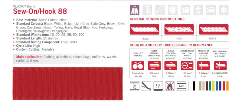
WHAT Combination, exactly are You using... lots of material options and important physical variety.
MIL-F-21840 CX FASTENER TAPES, HOOK AND LOOP, SYNTHETIC
A-A-55126 FASTENER TAPES, HOOK AND LOOP, SYNTHETIC
ASTM D5169 Standard Test Method for Shear Strength (Dynamic Method) of Hook and Loop Touch Fasteners
ASTM D123 Standard Terminology Relating to Textiles
ASTM D5646 Standard Terminology Relating to Seams and Stitches Used in Home Sewing
ASTM D6193 Standard Practice for Stitches and Seams
My company has design standards developed from tests and years of experience... perhaps Yours's does also... or an affiliate.
Or perhaps you need to run some tests of the materials that will be used [see listed specifications].
CAUTION: Constant use [O-C-O-C-O-C-etc], environment [sun, chemicals, sand, mud, water, etc] and laundering are all factors affecting long-term utility and reliability. In many cases [aviation] heat/cold/fire and environmental [ozone, etc] resistance are design factors. Also, installed tape-loads must be shear... with 'peel' only applied for opening/closing.
CAUTION: Selection/use of suitable/matched thread, cloth, webbing [textile tape], etc... and sewing practices ['the stitching']... are important factors. These affect available surface area and longevity of the Tape when in-position on the assembly... and must match the operational environment. Threads are available in natural plant fibers, glass-fibers, aramid or para-aramid fibers, Dacron or rayon or other mixed fibers, etc [choose wisely]. Choose stitching that is appropriate for the product... and does not blank-out [reduce] available hook/pile surface area.
Also... never hurts to evaluate/test similar products 'on-the-market'... especially sporting goods... that may have similar performance requirements.
Also, there may come a time when the product must be repaired in-the-field or back-shop to prevent further damage and restore utility. GIs hate when something can't be repaired in-time-of-need. A general maintenance, washing and repair document [printed or referenced on-line]… or fabric placard... could be useful. There is a joint Army/USAF manual for fabric items repair FM 10-16 / T.O. 00-25-120... 'General Fabric Repair'.
Regards, Wil Taylor
o Trust - But Verify!
o We believe to be true what we prefer to be true. [Unknown]
o For those who believe, no proof is required; for those who cannot believe, no proof is possible. [variation,Stuart Chase]
o Unfortunately, in science what You 'believe' is irrelevant. ["Orion", Homebuiltairplanes.com forum]
RE: (Velcro) Hook and Loop strength calculations under G force
IME, the glue gives up first.
www.sparweb.ca
RE: (Velcro) Hook and Loop strength calculations under G force
One of the first big, complex things I ever designed was a laser optical instrument to be installed in the customer's DC‑3. I designed a frame out of square 4130 steel tube. The system was fabricated, assembled and tested. At this point, I was informed that we needed covers for it. The laser was Class IV, so it had to be enclosed.
I solved the problem by designing a set of flat .032" aluminium covers retained by Velcro. You removed the covers by peeling the thin aluminium panel off from a corner. Everybody was happy. The customer was concerned about crash safety, but their DC‑3 was classified as experimental. The Velcro was retaining lightweight panels. Perhaps you have heard of DC‑3s!
Lessons learned:
- Anything with a high powered laser in it must be covered.
- Covers are difficult to design. The task must never be left for last. Cover design is an integral part of structural design, and DFMA.
--JHG
RE: (Velcro) Hook and Loop strength calculations under G force
another day in paradise, or is paradise one day closer ?
RE: (Velcro) Hook and Loop strength calculations under G force
Was that a SHOALS system?
In early 2001, I was "this close" to travelling to Wallops Island to support a... I don't remember what they called that one... "SHOALS-2" system. Then late 2001 happened, and my trip didn't happen.
I've done a few Dak mods myself. Consider 4 tanks the size of refrigerators on their sides, all full of diesel fuel to top up the generators in Antarctica & North polar science outposts.
www.sparweb.ca
RE: (Velcro) Hook and Loop strength calculations under G force
It was around 1983, and it was a Larsen 500 system, which eventually evolved into SHOALS. The devices were tested and used up in the arctic. Back in 1983, I got to visit the customer's DC‑3. Unfortunately, I did not have a camera. This is one of the reasons I got into photography.
Speaking of DC‑3s, Canadian Warplane Heritage just flew theirs, along with their Lancaster, over my house. Next time, I disable auto-focus.
I still have a baseball hat. If I lend it anybody, I make them memorise the acronym — Scanning Hydrographic Operational Airborne LiDAR Survey.
--
JHG
RE: (Velcro) Hook and Loop strength calculations under G force
The SHOAL's data acquisition unit was enormous. Like, 600 pounds.
Stiffness of the aircraft floor simulated (not very well but at least approximated) by the I-beams across the table.
Mounted to the seat-tracks and some of that structure is simulated by the other bars, too.
Not seen in the photos are the other restraints to keep the table from flipping over, or the Jeep winch to do the pulling, or the chains to keep the Jeep from sliding across the floor... it was a bit ad-hoc but the load was put and the rack was fine.
www.sparweb.ca
RE: (Velcro) Hook and Loop strength calculations under G force
An EDAK Rack! Those things drove me nuts. They are 19" rack shipping cases, not airworthy structures. That thing was operated without those covers, which provide quite a bit of strength and stability, especially side-to-side. Note how with the covers off, the anti-vibration mounts at the top of the cage are attached to the end of flexible cantilevers.
On later programs, I wrote specification controls that required the racks to survive 10G acceleration side to side without the covers and with our load, and the vendor agreed to it. I tried to explain to management that I could design a certifiably air-worthy 19" rack, and it would almost certainly be cheaper than that thing, but they never took me up on it.
--
JHG
RE: (Velcro) Hook and Loop strength calculations under G force
www.sparweb.ca
RE: (Velcro) Hook and Loop strength calculations under G force
I just visited the forum after many years absent from it and spotted your topic and wanted to respond.
I'm in AU and have been involved in many aircraft platform systems upgrades, modifications and repairs under the ADF system of technical airworthiness regulation for over 20 years. I have an aircraft structural engineering background on both fixed and rotary winged aircraft. I've been involved in supporting certification/design acceptance activities and the 'running system' on 'both sides of the fence'. I've exercised Design Review and Design Approval technical authorities of various narrow and broad scopes under the same system. I am also generally familiar with the CASG/DMO SPO and contractor engineering/maintenance environment having worked in it. I've also dealt with operational squadrons on engineering matters.
I note and concur with the general guidance and approach of SparWeb. I think I remember his informed commentary from my long distant visits to the forum.
Dare I ask - are you doing your 'engineering' in a squadron environment ? If so, I recommend you approach your applicable SPO's engineering organisation for guidance. General matters of configuration control and addressing basic aircraft certification/occupant safety requirements, mean that some record of what has been done (drawings, specifications, etc.) and the supporting analysis of its integrity (calculations, test records, etc.) are required. The SPO/platform CENGR or in-service support contractor's engineering cell should be able to assist.
While it's generally a good idea for enthusiastic squadron personnel (with the requisite manufacturing experience) to trial concepts such as this for implementation, it usually falls to the SPO engineering authority to approve such changes. Their 'buy-in' is required from the get go to ensure that these essential technical airworthiness and safety requirements are met, BEFORE too much effort is expended in developing the solution.
However, before you commit to the design exercise, I'd suggest you carefully consider what the important design and functional requirements are for this velcro-attached pouch. I don't require you to tell me the answers to the questions I pose. These are something of a 'reality check' for you in establishing what the functional and design criteria will be for this 'pouch project'.
Establish Design Specification
- Consult the CBD for the aircraft platform for restraint requirements for equipment located in occupiable areas (i.e. cockpit/flight deck, cabin, ect.)
- Calculate your design loads (emergency landing, flight inertia cases, etc.) with appropriate load factors for all directions (and fitting factors if necessary)
- Talk to the end users and establish what their access/use requirements are and try to negotiate with them a design solution which makes the design approval activity as least burdensome as possible (advice from the platform CENGR will assist you 'muchly').
Knowing the basics, you can then consider what the real functional (how will this be used ?) requirements are. Considering the overall attachment requirement for example:Means of attachment
- Is it absolutely necessary for the pouch to be removable from the larger bag (?)
- If so, under what circumstances ? In flight ? Frequency of access required ?
- How securely is the stowed item restrained in the pouch ? Is there a risk of it slipping out ?
- Can you modify the extant bag to incorporate the additional stowage provided by the new pouch ?
- Can you consider other stowage locations in the aircraft where risk of attachment failure/occupant injury is reduced ? (eg. stowage locker, FAK, etc.)
- Consider sewing/webbing straps (great tensile strength) looped through metal brackets with slots).
- Consider mechanical fasteners (press studs, standard parts, sheetmetal plates/rivets to 'join' bag-to-pouch, etc.)
Get permission to go and look at the cabin of the aircraft you are dealing with and look for examples of how discrete items of equipment are mounted in occupiable areas of the cockpit/cabin. Let these inform your design decisions. I have familiarity with mounting/relocation survival equipment in the cabin of a maritime patrol aircraft, in the ejectable crew module of a supersonic aircraft, in helicopter cabins, etc., including parachute stowages, fire extinguishers, crash axes, etc. so I'm familiar with the approach and requirements.I also encourage you to talk to the Life Support Techo in the squadron and they are usually all over this sort of stuff. I wouldn't be surprised if they produced the pouch. Yes ? They are a wealth of useful information.
I'll leave things there for now. My intent has been to give you an idea of the approach, rather than to provide a specific design solution and a raft of the kinds of calculations and data you require to substantiate the design. I will however caution you that you should seek materials/parts/fixings/etc. that have known, reliable and documented strengths/allowables. Consider using 'standard parts' and materials underpinned by specifications/standards. I''m thinking of the range of utility fixing/studs, etc. I've come across in the past, including Military Standard (MS) parts, and their current day commercially-managed equivalents. Beware of using 'internet-based data' for important technical data as much of the commercial/consumer data published online doesn't satisfy the principles which underpin what technical airworthiness is about, whether we are talking about the FAA, EASA, CASA of the ADF technical airworthiness regulatory environments.
I'll wind up with some personal opinions. I wouldn't want to rely on strips of velcro to secure anything in an occupiable area of an aircraft. It wouldn't be my first choice. I've seen units use velcro on the base of a carry-on laptop to prevent it from sliding off a work surface, but the laptop MUST be stowed securely in a stowage locker for take-off and landing for example. Get some professional engineering advice from your platform CENGR (or their underlings/contractor) BEFORE they are asked for their design approval/acceptance 'tick'.
A 'project' like this is a good way to cut your teeth on the many facets of what design engineering is about. I hope you find some utility in the exercise.
Good luck !
A (A30_737AEWC)