Continue to Site

Eng-Tips is the largest engineering community on the Internet

Intelligent Work Forums for Engineering Professionals

  • Congratulations cowski on being selected by the Eng-Tips community for having the most helpful posts in the forums last week. Way to Go!

Hi, Hopefully someone can help 1

Status
Not open for further replies.

Rwelch9

Mechanical
Apr 22, 2020
116
Hi,

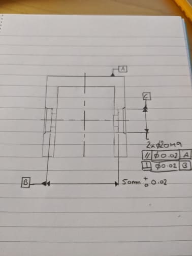
Hopefully someone can help me out i have two very small cylindrical pockets only 2mm deep.

They are coaxial cylinders on the drawing it reads 2x Ø20H9 with a Datum C call out next to it.

So i am assuming this means the constructed axis between these two features is the Datum C.

Does anyone have the correct way to dimension two cylinders that are a common axis ?

Any suggestions how to create these on my CMM

I am thinking of taking circles projected into the bottom planes of the pockets then constructing a line between the center points of the circles ?

Thanks
 
Replies continue below

Recommended for you

Rwelch9 said:
They are coaxial cylinders on the drawing it reads 2x Ø20H9 with a Datum C call out next to it.

Hi, maybe it's just me, but I'm having a hard time to visualize this. Please make a sketch and post it. What are the other datums? Standard ASME, ISO, Japan?
 
Cylindrical_pocket_drawing_ds2rvd.jpg


I have attached a small drawing that replicates my actual drawing.

Right now these pockets on the drawing have a common axis.

I thought it would be best having one as Datum C then use true position to control the 2nd pocket back to Datum C.

Any help would be appreciated.
 
Rwelch9,

I see a practical problem here in that the two cylinders are unlikely to be cut in one process. I don't like your datum feature[ ]B. You have to think through how this will be fixtured for manufacturing and inspection. You have a number of options.

[ul]
[li]Cut one cylinder and define it as a datum. Apply a positional tolerance to the other cylinder.[/li]
[li]Use the bottom, one end and a side as your primary, secondary and tertiary datum features. Locate both cylinder with profile tolerances.[/li]
[li]Re-think your design. If your accurate holes go all the way through, they can done in one setup, accurately. Whatever goes into your holes can be flanged.[/li]
[/ul]

Drafting problems have a nasty way of being design problems.

--
JHG
 
Hi Drawoh,

These two pockets are getting machined on a 5axis milling machine , there will be some error between them , then i will have to try find the true error between them and fine adjust the machine to try make the as coaxial as possible.

This is a drawing from our customer and i suggested changing it to make one cylinder as Datum and use true position to control the other pocket.

The problem i am facing with my CMM software is my primary and secondary Datums are both planes , My software only allows me to select one plane as a Reference . So in this case the secondary Datum which is the mid plane i cannot use.

i am also struggling to decide what is the best way to check it to allow me accurate results and information so i can move and adjust the CNC machine.

With regards to holding the part for inspection methods there is an internal pocket on the top face which we will use an expanding mandrel to clamp this part.
 
Rwelch9,

Its sounds like your customer is taking my second suggestion of three external face datum features. This makes sense to me. You should be fixturing to your datum features. The bottom face of your opposite hole certainly is not available for fabrication.

External feature always are accessible. If your internal pocket on top is not a datum feature, you should not be fixturing to it.

--
JHG
 
This goes with another thread i made regarding datum simulators ,


why do you have to fixture against the datum features . If i use the CMM

For example the part could be sitting not quite the same every time . Although when you take a plane feature on a CMM it will theoretically square your plane / part up.
 
Rwelch9,

You ought to fixture to your datum features when you fabricate. You cannot fixture to features you have not fabricated yet. If your datum features are the bottom, end and one side, you can mount the part in your five axis CNC, put a hole in one side, rotate your part 180[°] and put a hole in that side. You ought to inspect from the same datum features you fabricated from.

--
JHG
 
Rwelch9,

If your primary datum is a not-very-flat base, then you have a problem. You need something repeatable. If your holes are accurate, you need to locate them off of an accurate mounting face, and this should be your primary datum. Failing that, you can call up datum targets, so that everybody fixtures to the same thing.

--
JHG
 
For example the part could be sitting not quite the same every time . Although when you take a plane feature on a CMM it will theoretically square your plane / part up.

This condition is called "rocking", both Y14.5-2009 and Y14.5-2018 have ways to deal with it (candidate datum set and single solution respectively). Setting a part against a surface plate vs. sampling points and fitting a plane to it does not solve the problem, it only changes your issue from a physical one (physically rocking/shimming the part) to a mathematical one (fitting routines).

why do you have to fixture against the datum features . If i use the CMM

One could sample a surface and have a "virtual" datum feature simulator (or perhaps more appropriately as is referenced in the 2018 standard a True Geometric Counterpart), this is certainly possible. Use of physical datum feature simulators (aside from being utilized long before the pervasive use of CMM's and digital scanning tools) provide a consistent reference, are convenient when measuring multiple parts (either in series or parallel), large parts, or parts whose datum features are not easily accessible along with the features which reference them.
 
Rwelch9,
If you choose datum features based on how you make the part, you will very likely create tolerance stacks between the features that locate the part in its assembly in the product and other critical features. With unnecessary tolerance stacks introduced, that often means that tolerances need to be twice as tight to get the same level of quality from a functional point of view.

The datum features should be selected based on which features orient and locate the part to the mating assembly. Carefully examining the features as they mate with the rest of the product should expose one, or maybe a combination of two, feature(s) that constrain two rotational degrees of freedom, and probably also a translation or two at the same time. That should be the primary datum feature. The additional datum features should be those that constrain the part after the primary datum feature(s) have done their job.

If you look at the way the part fits into the mating assembly which feature(s) should be ID'd the primary datum feature?

Also, what CMM software is limiting you to select only one planar datum feature? Do you mean that it is looking for a plane, a line, then a point?

Dean
 
Hi dean ,

As we have the use of 5 axis milling machines etc . 9x out of 10 we can machine all the Datum feature in one single machining operation.

Unfortunately i am guilty of over using the CMM and i check mostly all of our components on the CMM.

If you take the small sketch i did previously i have a Plane as Datum Feature A Mid plane as Datum feature B then a line between my two pockets as Datum feature C

However using Aberlink M4 software . I can only use a Plane as a primary datum it will not allow me to use a plane / cylinder or any 3 dimensional feature as a secondary Datum.

On the CMM i can almost say i have never used a physical Datum Simulator . It will be a virtual simulator created by the CMM.

Something i have never had any problems with however starting to looking into ASME Y14.5 and most people on the forums etc .The seem to do it different.
 
Hi Rwelch9,
Are those datum features in your sketch selected based on how the part functions, or how it is machined?

It sounds like your CMM software is looking only for 2D features that would be a projection of features you probe down onto the primary datum plane you have established. I think the issue is how to best project those features down onto the plane. It will likely be difficult to model datum feature simulators properly, but that's the game with CMMs, as you probably already know.

What if the primary datum feature is a cylinder? Will your software accept that situation?

Dean
 
Dean,

Yes the Datum in the sketch are the the functional features.

They have been machined in 1 operation. Our machines are very accurate although if you take the two pockets in my sketch . The customer wants them as perfectly coaxial as possible. My job is try check it accurately enough to fine adjust this , which is very difficult and this is why i am asking different questions to see if my methods are correct or flawed.

I have confidence unless proved otherwise that using the CMM as using virtual simulators rather than take points on a vice or ground plate is a very accurate method . If the form is good . If my primary Datum plane was distorted for example then i would have a problem.

Yes exactly right about the 2d features projecting . So you have to very care full for example if i take a line or circle on the cmm that you project it into the correct planes.

Software will allow a Plane cylinder or cone as primary . then only 2d for your 2nd and 3rd Datum .

I am going to be changing software's very soon to PCdims which allow you to take planes and cylinders as secondary and Tertiary Datums
 
Rwelch9 said:
I have confidence unless proved otherwise that using the CMM as using virtual simulators rather than take points on a vice or ground plate is a very accurate method .

DRF_with_CMM_li8teb.jpg


Season
 
Hi Rwelch9,

I would start with a flatness tolerance on datum feature A. Then a perpendicularity tolerance relative to "A" applied to each of the two planar surfaces from which the datum B center plane are found. That perpendicularity could instead be applied to the center plane by placing it under the width dimension between the two planar surfaces, but there's no significant benefit and I think that adds difficulty.

Instead of the parallelism to A and perpendicularity to B that you show applied to the two cylindrical pockets in your sketch, I think:

|position|dia x.xx|A|B|

should work fine. To establish that datum reference frame (DRF) you need to find a center plane from the two planar datum feature B surfaces then project that as a line down onto datum A. If you then probe the two cylindrical pockets you should be able to get a result for that position tolerance. If would be much better if those planar datum feature B surfaces had a larger footprint. I'd be concerned that repeatability in rotation about the Z axis that those small planar surfaces can provide may not be good enough. If the repeatability isn't good enough then using the measurement results to tune the machining might turn out to be a "tail chasing" exercise. To avoid this it would be a good idea to set up the datum reference frame separately and independently 5 times, then check the repeatability of your results for the position tolerance on the cylindrical pockets. If the variation in your position values is greater than 20% then I wouldn't trust the data.

Also, is your CMM machine driven, or are you probing points manually? A machine driven CMM, and also iterating, to establish the DRF 3 times is necessary to ensure that you probe the same points accurately enough each time. This may sound odd, but think about the points you probe being located relative to the coordinate system that you're constraining with those same points. For the first iteration, you eyeball the probing locations, then establish the DRF from those points. The second time, you have the CMM drive to coordinates on the features that are relative to that first DRF, then establish the DRF from that second set of points. Repeat that one more time, with the 3rd iteration points located from the 2nd DRF you established and then that 3rd go at the DRF should be repeatable enough. If you come back and measure the part again, with that looping in the program as you establish the DRF, you should get a repeatable result. If you complete that iteration process and the DRF is still not repeatable, based upon variation in data measured relative to it, then the datum features may not be capable enough or some other source of uncertainty is causing the issue.

If your CMM is not machine driven, then getting adequate repeatability to enable reliable enough data to use for tuning the machining process is probably a long shot.

I think the functional requirement for coaxiality may not be super tight. They're so shallow that the mating pin/shaft may do fine with your first pass at machining the pockets..?

Dean
 
And I agree with what SeasonLee is pointing out about datum feature simulators, but almost every part on earth will have cylindrical or other datum features (such as the width between two planar surfaces that is datum feature B on your part), so building physical simulators that could be probed with a CMM becomes very difficult/expensive.

Since soft gaging is all that is feasible in many cases, the concepts of datum feature simulators have to be kept in mind. Then, even if the first attempt to establish a DRF isn't so good, a good CMM operator can do some additional probing of the datum features to look for errors in the DRF they first established, then do some shifting to improve the quality of the DRF. This additional work is in addition to the iteration and repeatability checking I mentioned above too, so accuracy costs time/money, of course. Failure to model datum feature simulators while establishing a DRF is the greatest source of error in CMM data, I believe.

Dean
 
SeasonLee,

I agree with Dean that using physical simulators is not the only workable option (and is often not workable because of the costs of building and maintaining accurate holding fixtures).

The situation shown in Figure 21 can happen, but it doesn't have to. The default algorithms in most CMM software were not created with GD&T in mind and thus create datums that do not follow the principles of datum feature simulator contact (and create major errors as shown in the figure). However, most software also contains other algorithms that can be invoked that do a better job. There are also specialized soft gaging software packages that do an even better job. There is always the issue of probing enough points, but the blatant datum creation errors can be prevented. The cost of more sophisticated CMM inspection would have to be weighed against the cost of physical fixtures.

Evan Janeshewski

Axymetrix Quality Engineering Inc.
 
Perhaps it is vocabulary - you have a single setup for a great number of individual machining operations. To make the cylindrical cuts requires a significant amount of repositioning, each of which allows some buildup in variation.

Datum simulators can be mathematically derived just as they can use physical datum simulators.

In practice the physical datum simulators are acting as analog computers making trillions of evaluations and will not be subject to numerical limitations; mathematical ones can't have physical defects - pick your poison.
 
Dean and Evan

You are right, thank you for your brilliant explanation, I personally think that CMM is just a measurement facility, in addition to the software we also needs some hardwares to match its functions, these hardwares are gage pins, precise measuring vise, collet, chuck, bench center, adjustable parallel sets, right angle plate...etc to simulate the features or datum features.

Season
 
Status
Not open for further replies.

Part and Inventory Search

Sponsor