Continue to Site

Eng-Tips is the largest engineering community on the Internet

Intelligent Work Forums for Engineering Professionals

  • Congratulations IRstuff on being selected by the Eng-Tips community for having the most helpful posts in the forums last week. Way to Go!

Skewed Connections Design Reference 1

Status
Not open for further replies.

MegaStructures

Structural
Sep 26, 2019
376
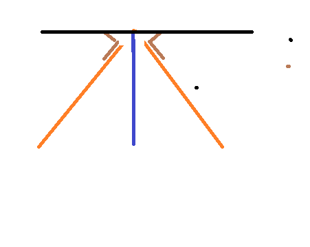
Looking for design references for this connection.

2019-12-13_18_05_10-Orthogonal_and_Skewed_Shear_Connections_Design_and_Detailing_Requirements_-_orth_a50ccq.png


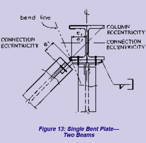
Have already found the following, but it doesn't show an example for this connection in particular. Link
 
Replies continue below

Recommended for you

In my experience, I've always seen a skewed connection like that with a bent plate, with a bend that makes an obtuse angle. The load path using a single angle as shown isn't efficient and makes the connection fairly flexible.
 
It's not my favorite connection detail, but I have a situation where there are 3 beams framing into one work point on the web of a girder. The middle beam is orthogonal to the girder and can get a conventional shear tab, but the other two skewed beams can't fit a bent plate, or skewed shear tab, because the shear tab of the middle beam is in the way. Enjoy my art.

skewed_beam_connections_jjsez6.png
 
Instead of using angles, could you use shear tabs that are pulled away from the web and welded to the flanges? The same skewed connection, except your point of contact is the top and bottom flange (no web) for the skewed beam. Pulling it back from the web would prevent interference with the center beam. The bolt access for that center shear tab would be the same.
 
I could weld a stiffener plate flush with, or inset by 1/2", to the beam flanges and then weld a skewed shear tab to that. The only problem I see there is that I will be adding a considerable amount of torsion to the girder by adding that eccentricity to my connection. I considered welding a plate to the flanges of the girder and making the connection shown below, but again my only issue is I don't want to add too much torsion to that girder, since it's end connections are shear tabs as well and there is no slab for torsional bracing.

2019-12-13_21_06_23-1999v05_connections_ahxo2t.png
 
Any chance this joint could not be concentric in order to simplify the connection. Based on the connection typologies you've been considering, it doesn't sound as though you've moving axial loads through this joint. Or are you doing delegated connection design and are stuck with what the EOR has shown regarding joint concentricity?
 
There's a possibility to move the beam if it is absolutely required, but it would effect some architectural features. These skewed beams are not directly in a braced frame, but they do double as the horizontal bracing for the floor, so they will transfer some axial force. Keep in mind these skewed beams are connecting to a girder anyway and not directly to a column, so changing the connection point along the girder should be of little consequence structurally speaking. The architect will definitely push back on changing the beam position if it is not necessary, but the structural integrity of the connection takes precedence here.
 
Just another idea for the heap. The roof of my local fitness club has some neat connections like this, albeit with five beams coming in. This takes up some space, naturally, and that may well be an architectural issue.

The detail also is not great for the transmission of serious axial. Are the beam top flanges at a common elevation? If so, maybe you deal with the axial with single gusset bolted over top of all the members.

c02_zlqoeh.png
 
I really like your first idea it takes care of the issue I had of adding torsion to the girder. Although it seems like a pretty complex connection at first it may also be easier to design, because none of the connections are actually skewed. The connection going into the bent plate/channel is orthogonal and the only force going into the channel is shear/axial, so the two sides of bolts should take an equal share of the force. That might be a winner
 
op said:
..it may also be easier to design, because none of the connections are actually skewed.

Yeah, that appealed to me to. The lazy, fee loving, direct load path craving part of me.

OP said:
Although it seems like a pretty complex connection...

It is. And it's a lot of parts and pieces. I'm pretty sure that skeletron has some first hand fabricator experience. If the connection has constructability issues, I'm sure that he'll set us straight.

I actually neglected to show one of the shear connections entirely in my sketch. I imagine that was obvious though.
 
Couple questions.

I like the gusset idea for taking axial loads (don't think it will be necessary here with my loads anyway), but I assume a gusset should be top and bottom. Wouldn't that make the connection a moment connection, or at least a PR connection with the flanges connected?

Are there any concerns with fin plates for instability under incidental torsional loads?
 
I suppose the gusset plate wouldn't need to be on both flanges and one horizontal plate on the top flange should be plenty flexible to maintain rotational ductility of the connection.
 
OP said:
Wouldn't that make the connection a moment connection, or at least a PR connection with the flanges connected?

It would.

OP said:
..but I assume a gusset should be top and bottom.

I'd envisioned only top, assuming fairly light axial loads for which the eccentricity in the members wouldn't be a big deal.

OP said:
Are there any concerns with fin plates for instability under incidental torsional loads?

What are you referring to as "fin plates"? The tabs/plates coming off of the channels? If so, I'd be inclined to design the bolted connections on those to resist moment as one would with a single angle bolted connection. In that way, you could envision that there's a hinge in plan at the plate bend.
 
I intended to use a shear tab in place of the single angles to stay consistent with the rest of the connections in the project. Really just a general question about shear tabs in general though. I don't believe there is any issue though. Thanks for your help!

400px-K1_Fig41_jom3hp.jpg
 
You're most welcome. I'm sort of surprised that this isn't a common situation with a simple, conventional solution. It's neat.

I see what you mean about fin plate torsion now. And yeah, I've never seen the eccentricity given explicit attention except in predominantly axial "cleat" connections.
 
Status
Not open for further replies.

Part and Inventory Search

Sponsor