Miami Pedestrian Bridge, Part XIII
(OP)
A continuation of our discussion of this failure. Best to read the other threads first to avoid rehashing things already discussed.
Part I
thread815-436595: Miami Pedestrian Bridge, Part I
Part II
thread815-436699: Miami Pedestrian Bridge, Part II
Part III
thread815-436802: Miami Pedestrian Bridge, Part III
Part IV
thread815-436924: Miami Pedestrian Bridge, Part IV
Part V
thread815-437029: Miami Pedestrian Bridge, Part V
Part VI
thread815-438451: Miami Pedestrian Bridge, Part VI
Part VII
thread815-438966: Miami Pedestrian Bridge, Part VII
Part VIII
thread815-440072: Miami Pedestrian Bridge, Part VIII
Part IX
thread815-451175: Miami Pedestrian Bridge, Part IX
Part X
thread815-454618: Miami Pedestrian Bridge, Part X
Part XI
thread815-454998: Miami Pedestrian Bridge, Part XI
Part XII
thread815-455746: Miami Pedestrian Bridge, Part XII
Check out Eng-Tips Forum's Policies here:
FAQ731-376: Eng-Tips.com Forum Policies
RE: Miami Pedestrian Bridge, Part XIII
https://www.ntsb.gov/news/press-releases/Pages/NR2...
Check out Eng-Tips Forum's Policies here:
FAQ731-376: Eng-Tips.com Forum Policies
RE: Miami Pedestrian Bridge, Part XIII
How have they done this in the past? I can imagine a board meeting to review a proposed report and approve or modify it as board members might think proper. But in public?
That must indicate this is the final thing.
Or maybe they want some public input? That could get out of hand fast.
RE: Miami Pedestrian Bridge, Part XIII
At some point the draft will be circulated to all parties for more detailed comments, support, and objections. This is typical in major aircraft accidents where recommendations are being made; there is no point in the NTSB making an impossible recommendation and they recognize they can't know everything.
This is part of why it seems to take so long - the goal is to test assumptions as to what the underlying factors are and that proposed fixes will actually make for better outcomes.
RE: Miami Pedestrian Bridge, Part XIII
Edit - the post was removed/deleted
RE: Miami Pedestrian Bridge, Part XIII
The people who have actually studied the available failure info and have written reasons why the lower PT rod in member 11 could not have broken impress me. You ramblings don't so much, meaning I have no want to impress you back.
RE: Miami Pedestrian Bridge, Part XIII
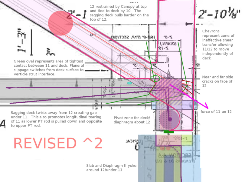
When the structure was on the form work and the lower PT rod was tensioned, it served to hold the flaky joinery tight. Although the strain was already pulling at the joinery and causing the cracks to show when the formwork was removed, the full magnitude of the problem had yet to be revealed. The structure was then moved and set in place with the lower PT rod still hiding the issue. When the PT rod was detensioned, the structure settled with the slab sagging and the top of the diaphragm pulled toward the center while 12 bowed out carrying the load transmitted down 11. The structure held in this degraded form until the lower PT rod was retensioned (to the max). This activity had no leverage to pull the structure back into shape. The significant force vector from the retensioning of the lower PT rod is the horizontal component that is pulling the slab (by way of the tab) toward the center of the structure, amplifying the tearing of 11. The structure sags further building the load on 11 etc.
RE: Miami Pedestrian Bridge, Part XIII
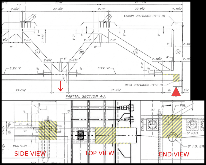
your top view doesn't show the 2 or 3 tubes set into the deck which appear in some drawings and not others and have a high suspicion factor about removing the interface between 11/12 and the deck. IMHO.
Remember - More details = better answers
Also: If you get a response it's polite to respond to it.
RE: Miami Pedestrian Bridge, Part XIII
First - you present a good description of your thoughts. Second - the graphics are very helpful. They were seen as such when first presented. I will use interrupted quotes as a means to assist my comments.
I would view this using the deck as the constant - it is the largest single element in the structure. It is 31 feet wide and 174 feet long and weighs about 1150 kips vs 16 kips kips for member 11. So I would describe the action as member 11 being forced across the deck and out the end of the deck. I am not sure there was a lot of sagging before node 11/12 went into full failure mode.
Full agreement here.
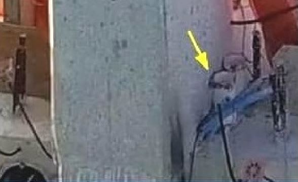
Since the lower PT rod remained anchored in the deck, and that anchor did not move (within our ability to see at this time) it seems more appropriate to view member 11 as having an unresolved force at node 10/11 from the PT rod tension, with the lower PT rod pulling node 10/11 to the north with the horizontal component of the 280 kips of rod tension. We have seen a picture of a longitudinal crack in the west side of 11 about 6 " above the bottom and maybe within a foot of the fillet between 11 and 12. I read this as the beginning of the splitting of 11 which resulted in the upper part of 11 sliding north and off the end of the deck, with the bottom of 12, while leaving the lower PT rod anchored in the deck.
Fully agree. The failure of node 11/12 to remain connected to the deck left two load paths to deliver load to the pylon - the Deck and the canopy. With both acting in bending only they failed immediately.
Thank you.
RE: Miami Pedestrian Bridge, Part XIII
It's ridiculous how basic the explanation is once all the clutter is removed.
I would add that 12 also required being tied longitudinally into the deck as it would be a robust backstop for 11.
RE: Miami Pedestrian Bridge, Part XIII
SF Charlie
Eng-Tips.com Forum Policies
RE: Miami Pedestrian Bridge, Part XIII
Docket And Docket Items
Happy searching.
SF Charlie
Eng-Tips.com Forum Policies
RE: Miami Pedestrian Bridge, Part XIII
Is interesting
SF Charlie
Eng-Tips.com Forum Policies
RE: Miami Pedestrian Bridge, Part XIII
(show members after collapse...)
SF Charlie
Eng-Tips.com Forum Policies
RE: Miami Pedestrian Bridge, Part XIII
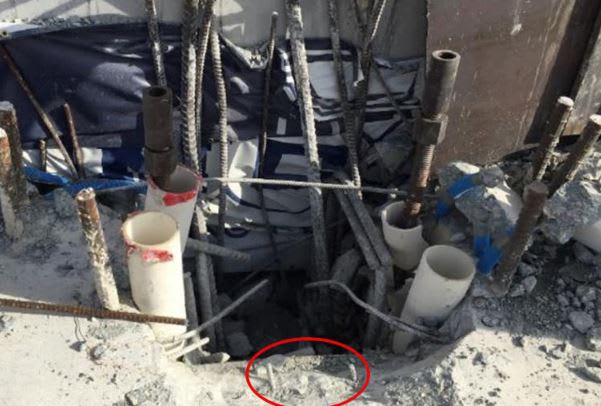
So the deck surface delaminated about an inch below the surface in areas larger than the contact zone for 11 and 12.
I hope they at least hammer tapped the surface to establish the extent of that delamination thru sounding. Ultrasonic would be better.
I have to wonder if there was a problem in screeding the deck surface and more concrete was added at this area to make grade. That could have created a lack of aggregate across this zone, and created an unintentional pour joint. Bummer location.
Plenty to ponder here. Quite a release of docs. I see FIGG found the SF to be 1.25 for shear friction under 11 and 12, thus proving it should not fail. The overall SF for horizontal shear friction between webs and deck was more than 11. Good head fake there.
Much to digest.
Thanks for the link.
RE: Miami Pedestrian Bridge, Part XIII
In that prelim report, a callout refers to the lower PT rod in #11 as "sheared," implying that it had failed in shear during the collapse. However, the evidence of other photos and diagrams is that the rod was intact after the collapse, and had been cut after the collapse in the process of relocating key portions of debris for later use in the investigation.
New reports available in this docket correct that misconception by omitting references to the "sheared" PT rod, and including photos depicting it as intact.
RE: Miami Pedestrian Bridge, Part XIII
I believe that two things are obvious: 1) Concrete truss design is complex, and should not be attempted without exhaustive research to establish the appropriate parameters, and 2) Shear friction as a concept needs a lot of work.
RE: Miami Pedestrian Bridge, Part XIII
I find pics # 71,88,89,90,92,and 93, plus #102 very revealing. Scary, actually.
My take is member 11 was in bad trouble and the base of 11 and 12 was outbound.
Also it appears the first hoop of #7 shear -friction reinforcing across the plane at the top of the deck was intact after the collapse. That reduces the contribution of the reinforcing. Apparently the south most hoop was in the fillet under #11 and did not share much shear load because the cracking in 11 was north of that hoop.
RE: Miami Pedestrian Bridge, Part XIII
Brad Waybright
It's all okay as long as it's okay.
RE: Miami Pedestrian Bridge, Part XIII
Me too.
After reading some of the docket, it appears parties involved were right and correct, yet wrong. (edited - don't want to go there)
I think the bridge was so massive, they did not feel it could collapse from little cracks. I have severe fear of heights, yet I can look out airplane window with no worries, yet I sweat profusely on a 16 foot ladder.
I feel following link is most interesting. The illustrations inspire me.
Bridge Factors Attachment 73 – FHWA Assessment of Bridge Design and Performance
https://dms.ntsb.gov/pubdms/search/document.cfm?do...
RE: Miami Pedestrian Bridge, Part XIII
The picture below shows, to me at least, a large discrepancy in resisting forces on the top and bottom chords.
I.e. the top chord has a lot more force going right and the bottom a lot more going left. In a classic truss design these forces are roughly equal.
But here we have large discrepancies (about 2000 kips) which I don't see being taken into consideration anywhere. The rather puny columns at the end aren't going to resist anything much so where does all this out of balance force go?
I know this is a simplification and that the truss was supposed to be rigid, but this really doesn't look to me that these out of balance forces are being accounted for. But then I'm not a civil design engineer, but I would like to know what is happening here.
Remember - More details = better answers
Also: If you get a response it's polite to respond to it.
RE: Miami Pedestrian Bridge, Part XIII
I am struck by the clarity of the presentation in this document. Compliments to the authors. It is easily understood.
I find this part interesting - and damning to those at the March 15 meeting. From page 66 of 90.
Many items are eerily similar to points and illustrations previously presented in this forum. Kudos to all.
RE: Miami Pedestrian Bridge, Part XIII
I see what you are seeing.
Where does that diagram originate? I think I have seen it but do not recall.
I can't believe that everything from the south end adds to a value at node 10/11. The arrows seem to show the horizontal shear from the diagonals but I am not sure.
Are they superimposing the PI forces?
Thanks,
RE: Miami Pedestrian Bridge, Part XIII
My thoughts as to shear friction - it seems that 1) there was no preparation of the construction joint area at the deck surface which would have required more steel across the joint; 2) the cracking of Diaphragm 2 from vertical load severely reduced the capacity of any steel in member 12 to contribute and that reinforcing should not have been considered as contributing; 3) that same cracking of the diaphragm reduced the punch out capacity severely; 4)as discussed here before and by FHWA, the clamping force from transverse PT was overestimated; 5)leaving the need to provide enough reinforcing across the construction joint to resist all loads, which was not done (woefully inadequate amount provided); 6) the FHWA report discusses cohesion, which FIGG properly disregards, and was lost before the bridge was lifted by the transporters - the first cracking is evidence of loss of cohesion.
My takeaway is that with another half yard of concrete and half ton or ton of reinforcing at node 11/12 and node 1/2, and with proper joint preparation, the bridge would be standing today. There may be other problems yet undetected, but it would not have failed on March 15, 2018.
And there is much yet to be learned.
Thanks for the opportunity to comment.
RE: Miami Pedestrian Bridge, Part XIII
Remember - More details = better answers
Also: If you get a response it's polite to respond to it.
RE: Miami Pedestrian Bridge, Part XIII
The simple truss analysis of years ago assumed things were rigid members with pinned joints. Reality can be different.
The killer "Finding" ----------
I do not comprehend the difference between FIGG calcs and the NTSB results - - anyone???
Surely FIGG will have a comment.
In a previous post I had said "There may be other problems yet undetected" - this may be one of them. If the NTSB report is correct March 15 may have been the most fortunate date available.
RE: Miami Pedestrian Bridge, Part XIII
The Feds ran 4 runs and got different answers each time - by maybe 10% - maybe more.
Strikes confidence in me.
RE: Miami Pedestrian Bridge, Part XIII
End vertical reactions are pretty much equal. Member 2 is much flatter angle than 11, so there is a greater horizontal component thrusting into the canopy and pushing on the deck than at member 11.
So it appears that to balance shear loads to the canopy we take node 2/3 at 2182 kips AND ONLY 464 kips northbound at node 4/5 for a total of 2656 kips and that will balance all the remaining shears pointing southward. So the arrows are backwards on several nodes.
Am I not corect?
Same idea for the deck. And arrows are pointed the wrong way there too.
I am basing this on a free body of the canopy - horizontal forces into the canopy must balance to zero or the canopy will wind up in Sweetwater.
RE: Miami Pedestrian Bridge, Part XIII
"I don't know".
Interview of EOR March 20, 2018.
RE: Miami Pedestrian Bridge, Part XIII
https://dms.ntsb.gov/public/62500-62999/62821/6285...
...which includes Figg's own "probable cause":
Um, yeah, good luck with that.
RE: Miami Pedestrian Bridge, Part XIII
SF Charlie
Eng-Tips.com Forum Policies
RE: Miami Pedestrian Bridge, Part XIII
Maybe when the language used in the report, is the result of a negotiation between the forensic investigators & the client.
The report puts a lot of focus on the roughening of the joint between the deck and #11 and rightly so but the in the few instances where surface prep was called out, I do not believe they ever added (TYP.). It would have made a world of difference.
Concrete finishers love their hand tool. I wonder if a small hand cultivator would be an acceptable means of roughening the concrete before it completely hardens.
RE: Miami Pedestrian Bridge, Part XIII
I can't argue that the joints didn't get the prep they ought to have. But I think that if you're in the realm where the absence of 1/4" surface roughening in a construction joint causes your bridge to fall down under its own weight, your design embodies way too little margin of safety.
RE: Miami Pedestrian Bridge, Part XIII
Bridge Factors Attachment 73 – FHWA Assessment of Bridge Design and Performance
https://dms.ntsb.gov/pubdms/search/document.cfm?do...
FHWA finds FIGG underestimated nodal shear demand at 11/12 and deck. FHWA represents FIGG calculations as showing shear at 11/12 to deck to be twice as great (approx) under full two span condition than when under single main span with full fixity at the pylon/pier (north end of main span), and the greater value should have been used for design and was not. Both conditions are noted to be Stage 4.
Note the Fixed Pylon (Stage 4) is an intermediate construction stage subject to construction loads only. Failure prevented this condition from being encountered.
Note also that the Longitudinal Model (Stage 4) is also an intermediate condition subject to construction loads only.
I do not see how it is possible for moments at the north end of the main span to be greater than when full fixity is assumed at that end. Unless one condition is unfactored DL only and one is full factored DL and LL.
First, DL is about 11 kips/ft and LL is 90#x30 feet = 2.7 kips/ft. Factored that is 11k X 1.25 = 16.75 kips/ft DL and 2.7 k X 1.75 = 4.37 kips/foot factored LL for a total of 18.5 kips/ft factored load. The factored TL load is 1.67 times unfactored DL. So the 2X increase was not from considering unfactored DL vs factored TL. Factors are FHWA representation of those used by FIGG.
The only way I can see the shear demand in node 11/12 to deck increasing beyond that from full fixity at the pier is if enough negative moment is created over the pylon by the continuity PT in the canopy to draw even more load from the main span to the pier. But that condition is Stage 5, after the north span has cured.
So I am confused as to how FIGG could have had such a discrepancy between shear demand at node 11/12 to deck under Fixed Pylon (Stage 4) vs Longitudinal Model (Stage 4) conditions.
As I recall prior discussion here the unfactored DL shear at node 11/12 to deck was in the order of 1300 kips. Or was that the axial load in 11? Adding LL and factoring the loads by the 1.67 from above (DL to Factored TL ratio) yields 2170 kips - pretty much what the graph by FHWA shows for 11/12.
Perhaps FHWA is misinterpreting something also?
Whatever the answer, this points out the complexity of this design and the various support conditions which existed - full form support, full span at casting yard, intermediate span during transport and reversal of loads in many members, and final support in place. All happening in a brittle structure.
And if the non-redundant factor is only 1.05, that would not have saved this structure at this phase.
RE: Miami Pedestrian Bridge, Part XIII
I should have been more specific. Thanks.
RE: Miami Pedestrian Bridge, Part XIII
The tool you recommend cannot be approved. First, it requires a seat, a safety belt, and special gloves.
Seriously - I think special provisions for joint preparation should be made at joints as critical as node 11/12 to deck. The demand and unit stresses and performance required are so much greater than in any construction joint in a pier or wall or at the top of a girder to a composite slab. So I think special forming is required. I suggest formed indentations in a 45 degree shape with amplitudes greater than the largest aggregate size.
Forget cohesion - the slightest slip has destroyed that. Forget raking it - heck, I have seen bridge decks with amplitudes greater than 1/4 inch. So often raking results in dingleberries which are easily dislodged by structural loads but are not loose so washing does not remove them. And yet raking is one of the predominant method of preparation for a joint.
The sawtooth configuration will develop the tension in reinforcing across the interface while the aggregate can move into the "teeth" and those areas will act like concrete instead of paste, dingleberries, and ball bearings. If reinforcing creates access problems great - make the shear plane bigger. If this project demonstrates anything it is "get enough".
RE: Miami Pedestrian Bridge, Part XIII
Shear friction is not mentioned in the Australian concrete standard AS3600, but I know that some Australian engineers use it at times under pressure of contractors who don't want to provide decent bearing at joints.
RE: Miami Pedestrian Bridge, Part XIII
I have not ran the numbers - that took FHWA 18 months - but in concept the increase in load at node 11/12 to deck may be due to the details of staging the construction.
Calculating for fixity at the pylon end (north) of the main span under dead load is unrealistic - that could only happen if the span were again supported or lifted along its length and then fixed. So calculating fixity at the north end of the main span should only apply to added loads after it is connected to the pylon and north span.
Thus shears at node 11/12 to deck would be from full DL of the main span as simply supported PLUS added load on the main span under finished condition PLUS load drawn from the main span due to negative moment produced over the pylon from removing shoring under the north span and from the continuity PT force added in the canopy under Phase 5.
In concept it appears the loads on node 11/12 to deck could increase. I do not see how they could double - but I have not ran the numbers.
So I get the following approximate added load (vertical) to contribute thru whatever angle to cause shear in 11/12 to deck. All calcs by "back of envelope" method and to that accuracy. Remember - this is the increase at the end reaction of the main span and must be adjusted to show actual shear in the node. So compare only the loads causing end shear.
First, LL from the main span will add about 300 kips shear in the main span at the pylon and is the major thing that will influence the node shear. But this does not allow us to compare the effect of releasing the north span. I propose to do LL and released DL on the north span to see maximum influence on node 11/12 to deck from that action.
Distributing the released DL from the north span to both spans with spans fixed to pylon adds 14 kips shear to end reaction of main span at pylon. Loading LL onto north span only increases shear at the north end of main span by 4 kips. General concept is Unbalanced Moment X stiffness factor of main span / stiffness factor of both spans and pylon.
The pylon, if fixed to superstructure trusses is rather stiff becaus it is short. Pinning the top of the pylon increases the draw of shear to north end of main span to a total of 34 kips. At 32 degrees, that is about -what - 60 kips in a connection that has 1300 or more? Insignificant. Remember - all numbers unfactored. The fixed end moments of DL and LL from the short span remain mostly in the short span because the long span is less stiff, and the shear draw is M/L.
Would appreciate someone checking me out - for a pinned top of pylon the distribution is simply L/(L1+L2) and with same bridge section on both spans it is rather easy.
I find it interesting today because if I do it right it keeps me fresh. If I screw up, I gotta make adjustments to my thinking. So feedback is welcome.
Anyway, I still cannot see the shear at node 11/12 to deck doubling from the release of the north span.
RE: Miami Pedestrian Bridge, Part XIII
At the risk of being accused of Monday Morning Quarterbacking, I put together a quick sketch showing an alternate way to create the interface area. This is based on Figure 56, on Page 60 of 90 in the Bridge Factors Factual Report Attachment 73.
The sketch shows a buttress above the deck surface that would be placed with the floor, making it monolithic with the floor. The shear plane would not go through a cold joint. The Interface bars would be angled, The resulting cold joint would be in pure compression.
Thoughts?
RE: Miami Pedestrian Bridge, Part XIII
Since this is such a critical requirement, would it make sense to restate this requirement on the Drawings so it's right there in front of the Contractor? Or does that create a slippery slope that would end with repeating the entire referenced document?
RE: Miami Pedestrian Bridge, Part XIII
And to transfer the tear out force to a point where the PT in the deck can handle the load it will need longitudinal reinforcing well anchored under the joint and extending far enough south to transfer the load. Had these ideas been at work on March 15 the structure would be standing today, IMO.
Absolutely. My office issued many many drawings over 40+ years and in every case in which construction joints were needed we included a note in the general form of "Construction joints shall have surfaces removed to expose aggregate solidly embedded and remove all laitance ---" etc. And that was for tops of foundations under walls, joints in walls, - - not in something with the demand and critical nature of node 11/12 and the deck.
Which brings me to a comment about aggregates. In many photos of the damaged structure I see what appears to be fractured aggregates embedded in the cement matrix - and though the photo is a 2D image it apppears the aggregates fractured in the same plane as the matrix. In the use of light weight aggregates there is a requirement for "splitting tensile strength". I wonder if the aggregates used are appropriate for 8500 psi concrete? It seems to me if you want to make 8500 psi concrete you need 8500 psi aggregates with suitable shear strength. I am aware that FHWA found the concrete to be suitable for the design requirements by FIGG.
RE: Miami Pedestrian Bridge, Part XIII
Figg made a valid point that their involvement during construction was limited. My project managers don't like to send me to the sites either because of my billing rate, and it becomes very annoying when the inspector calls in with questions that should have been addressed before they become a problem in the field. The person who does the design is in the best position to see things before they become a problem, and even allow minor deviations that accommodate a contractor's concerns without compromising the work. I wonder if Figg was tempted to take the position that if they can't be on site then it's not their problem. This could point to an issue in the construction process and the contractual arrangements between the various entities.
I wonder who is paying for all the forensic work?
RE: Miami Pedestrian Bridge, Part XIII
The design process can involve maybe hundreds of decisions each day. The litigation process can spend maybe hundreds of hours on just one of those decisions. It does seem that, for the most part, after a year and more of posturing, most of the parties in this event have decided to avoid litigation and settle.
I applaud that.
RE: Miami Pedestrian Bridge, Part XIII
SF Charlie
Eng-Tips.com Forum Policies
RE: Miami Pedestrian Bridge, Part XIII
Your concept is theoretically acceptable but is more difficult to build/form. There are also other joints that were an issue which would also have to be altered. There is actually more shear at the #10/#11 joint than the #11/#12 joint but it was not an issue since the PT from #10 came through the canopy and up into the blister to form a shear plan on the upper side of the canopy (the PT also clamps the joint). Although the shear stress across the pour joint was still very high.
The steel was actually not that congested (at the slip plan directly below #11). I would increase the base as you have shown, increased the steel (as you have shown) and roughened the surface. For ease of construction, I would keep the pour joint at the top of the deck but make sure my stresses were low enough to be adequate. The steel should all be ties for good anchorage for shear friction.
I would also say, under similar circumstances, I have had hassles from rebar suppliers. They don't like to make each tie a different height. It is more labour and difficult for them to organize. Although I would say that the extra complication is worth in this case.
The other option would be to organize a continuous pour of the deck and diagonals. You could form the a square end at the top of the diagonals and then pour the canopy. You don't want to pour the canopy with the diagonals because of the plastic creep issues. You can get a gap between the diagonal and the canopy.
RE: Miami Pedestrian Bridge, Part XIII
As for the canopy, I have thought that a continuous concrete beam should have been cast full length under the canopy, providing rotational resistance to those joints and plenty of area for shear transfer - something like a bridge deck on a bridge girder. That might leave the plastic creep issues you mention, however. What are your thoughts about creep and elastic shortening of the canopy from PT forces relative to its effect on the already cast diagonals?
It is interesting how many opportunities there are for 'improvements' to this structure. Points out the complexity of the idea.
RE: Miami Pedestrian Bridge, Part XIII
Doing a continuous pour takes some experience. We sometimes do it for footings and walls/columns. You have to go back and forth on the pour. This also does not work with high slump concrete but it is done. In my area, it is actually common for house strip footings and foundation walls.
I don't have my code at home but I think it is 1.4 (I can check later). It may also be slightly different in the US. A continuous pour makes the failure plan no different than a failure plane in a typical column. If you look at Figg's report from the NTSB docket, they actually made columns will deliberate cold joints to simulate the failure plane of the bridge.
I though of a continuous beam on the canopy as well but that would have to be poured with the diagonals as well to get an advantage. You might as well pour the canopy with the diagonals.
If you have a true determinant truss, the PT does not affect the member forces in the diagonals or end verticals regardless of the creep. However, you do not have a true truss (nor do you ever have a true truss in the practical world). The bending stiffness of the canopy, diagonals, verticals are affected to some degree by the PT. You can argue that if you have enough ductility demand, it really doesn't mater in terms of safety. Elements like #1 would have double flexure due to the PT. The PT would cause visible damage but not critical damage as the axial stresses due to gravity load on #1 are low. The only way to know for certain what the effect of the PT would be is to model it. Even a simple 2D stick frame could be used to do this. To cause high shear forces at the joints with the PT would require the deck and/or canopy have a relatively high bending stiffness compared to the truss as a whole. In general, creep reduces the level PT force as the structure essentially softens with response to long term loads. Any deleterious effect from the PT would also likely diminish with creep. When I have had a complex PT structure, I model concrete both long term and short term. I reduce the E for concrete but keep the same temperature difference on the PT to determine the relaxation due to creep.
RE: Miami Pedestrian Bridge, Part XIII
*Referring to the drawings below, the debate seems to be that the dry joint should have followed the orange plane, and not the blue plane.
*This debate is irrelevant because the failure did not occur along the blue plane; and, the orange plane would have made no difference.
*The joint failed along the two red planes identified in the Side elevation and the Top View.
*Specifically, the surfaces that failed under sheer load are the two surfaces identified as having dimensions b x c
*If you calculate how much steel is required to hold 1500 kips in strut #11 from moving northwards, you will find it needs about 25 square inches of steel.
*If you study the drawings, you will find perhaps 5 square inches of steel crossing the red planes (b x c) that might act as an anchor against strut #11 moving northwards. The concrete itself adds no resistance, because across these red planes, there is no clamping force.
QED
RE: Miami Pedestrian Bridge, Part XIII
I have read though some of the reports online and would like to learn something from this to improve my own designs. So far the main takeaway I have is that where critical constriction processes are needed (such as roughing the surface) to call it out instead of referencing standards.
The second takeaway I have is using shear keys any time I have a critical cold joint.
RE: Miami Pedestrian Bridge, Part XIII
I am not quite sure what you mean. The failure plane was the blue plane. Figg actually did a calc on the pink planes in their presentation just before the collapse. It was not a critical link in the chain. They missed the blue plane which was the weak link in the load path.
There is a clamping force from the transverse PT that rests shear friction through the pink planes. The is also a tonne of bars in the deck and diaphragm. The shear stress is substantially less since there are two shear planes. The mu value is also much higher since is part of a monolithic pour.
RE: Miami Pedestrian Bridge, Part XIII
It is good practice in such a situation to use keyways. Our code does not have a means of calculating the shear friction at a keyway. It is part cold joint and part monolithic. It adds capacity but calculating the shear resistance is not necessarily easy.
Beware, using keyways can cause issues as well. The contractor can accidentally leave the wood blocks in place which makes the joint worse off. I don't like keyways where they aren't a significant benefit. I use to see them at strip footing and wall joints but these joints have low shear and it isn't necessary. That practice has tended to fall to the wayside.
RE: Miami Pedestrian Bridge, Part XIII
Figg's calcs are worth nothing. That is why there was a collapse killing six innocents in the first place.
If you look at the cracking that was observed (see 1st photo below), you see that it passes through the two pink planes at 45 degrees (see 2nd drawing below).
There are NO photographs of the cracks passing through the blue plane - obviously, because none were observed.
Also, my point is that there is missing an amount of about 25 square inches of steel to TIE back strut #11 to the deck. Strut #11, with 15000 kips (15 million pounds) is simply not connected to the deck for any tensile forces. You can almost see strut #11 moving northwards in real time for want of being tied to the deck. This is proof positive.
There was not "a tonne of bars" crossing the pink plane. If you look at the relevant drawings, there were maximmum five (5) square inches of steel crossing the pink plane, and all of those were too short to develop any tensile load in those bars.
RE: Miami Pedestrian Bridge, Part XIII
The calculations done by Figg on the pink failure plane were not incorrect. It just wasn't the critical failure plane. They calculated the strength of the wrong link in the chain. It is the pour joint that is critical. The area is less, the steel through the joint is less and the mu value is less. The north end of the failure plane near #12 did punch but that was because there was a concentration of vertical steel in #12. The primary failure plane was the blue plane. The vertical steel in #12 was what held it together until the PT in #11 was re-tightened.
There is tonnes of capacity in the pink plane. It was never an issue. The #11 diagonal itself would fail in shear before the pink plane.
RE: Miami Pedestrian Bridge, Part XIII
Yep. Shear friction is upper bound, yet people treat it as lower bound.
You can’t just consider one failure surface.
Spoiler:
RE: Miami Pedestrian Bridge, Part XIII
My question w/ the FHWA 73, on page 84 in Table 3, they list Avf available for shear capacity. At all nodes they consider the bent #6 & #7 bars as engaged and fully developed. I would question this finding and argue against incorporating these bars into any Avf shear capacity. Or maybe if you were to use them, use them only at some fraction of their whole. IMO, they are not properly developed on either side of the shear failure plane, as required by code.
RE: Miami Pedestrian Bridge, Part XIII
If the pink plane was not the critical failure plane, then:
1. How come the photographs show catastrophic failure across that plane?
2. How come there are no photographs of catastrophic failure across the blue plane?
RE: Miami Pedestrian Bridge, Part XIII
You are correct. I wouldn't such otherwise. However, there are literally an infinite number of possible failure planes. As an engineer you have to rationalize the failure planes that need to be checked. I am also not suggesting you shouldn't or don't need to check the pink planes of failure.
RE: Miami Pedestrian Bridge, Part XIII
1) I already answered this earlier. #12 has a concentration of vertical steel which helps transfer loads across the blue plane but this is just below #12 and not the rest of the shear plane. That is why you get localized punching at #12.
2) There are photographs of catastrophic failure across the blue plane.
RE: Miami Pedestrian Bridge, Part XIII
Really? Can you pass those on? I have studied all the photographs carefully. They are not in the record.
RE: Miami Pedestrian Bridge, Part XIII
Check out page 96 of the OSHA report. This photos is other places as well.
https://www.osha.gov/doc/engineering/pdf/2019_r_03...
RE: Miami Pedestrian Bridge, Part XIII
My point would be to check the shear in whatever section remains to resist shears.
Thank you.
RE: Miami Pedestrian Bridge, Part XIII
I am not sure a fully understand. However, when I do a key design I will use 2x4s spaced at 7" centres (or 2x6 spaced at 11" centres) oriented perpendicular to the shear force. That way, the shear is forced to go through about the same amount of monolithic concrete from the first and second pour. I am not sure if that what you means by an equally balanced key design. If you have just one big key, it is just pushing out one end and you are back to the same/similar problem. If that you what you are saying, then I agree.
RE: Miami Pedestrian Bridge, Part XIII
Earth314, the photographs at page 96 show that the failure plane was on a combination of the blue plane and the pink plane. Close to the green plane shown below.
However, the fact is that we have a horizontal force in strut #11 of 1,500 kips going north. For equilibrium, we must have enough resistance to hold 1,500 kips onto the deck going south. Therefore, we must find 25 square inches of steel configured to pull in a southerly direction into the plane of the deck. Those 25 square inches must somehow CONNECT to the load in strut #11. The vertical bars in strut #12 have no southerly component and so don't count towards this requirement.
Is it being suggested that by roughing up the surface of the concrete at the blue plane cold joint before pouring strut #11, this would be sufficient to eliminate the need for 25 square inches of steel pulling south?
RE: Miami Pedestrian Bridge, Part XIII
This was previously posted and deleted so I could clarify items. Here it is again.
The subject of clamping force on the sides of the assumed shear plane where 11 and 12 punch thru and out the end of the deck is interesting to me. The conditions surrounding this failure provide an opportunity to examine the concept of shear friction. I would like to discuss, hopefully not alone, the shear friction concept as it could apply to a "clean" version of the FIU bridge, north end of main span.
The conditions at hand are certainly not 'clean' as this was a multi phased failure with prior cracking at the deck surface for one zone, failure plane defined by the void created by the lower PT duct in member 11, the presence of 4 - 4" dia pvc ducts, proximity to the end of the structure, and presence of already cracked end diaphragm 2, to list a few.
If this were to have occured in an area of deck fully surrounding the zone, it would have been much like a column in a flat slab. Failure would be mostly in diagonal tension and be reinforced for that. Portions of this failure developed into diagonal tension as it neared the edge or end of the deck, and that zone was already cracked by the load in the diaphragm. The diaphragm cracking may have loosened things up for the blow out - or maybe the other way around.
For for discussion and clarity, I would like to just discuss the shear friction issue. My purpose is not to declare some concept as the final thoughts but rather to elicit discussion and consideration of conditions unique to a simplified modeling of this failure. There are many present here with experience, understanding, and inquisitive natures with much to contribute. I hope something in this will interest you.
If reinforcing steel across the shear friction plane can provide shear capacity because it goes into tension and that is measured by 0.9 times yield or 57,000 psi lets see how much stretch that requires to develop 57000 psi (or whatever - the principle remains). Using a #7 bar and development of maybe 24D = 1.12"X24 =27 inches. If tension in the steel is zero at the embedded tip and 57,000 psi at the interface, the average is 28,500 psi and stretch is 28500X27/29,000,000=0.026 inches on one side. Then if the same embedment stretch develops in the other side of the interface there is a total of 2X0.026=0.052 inches gap in the interface at full factored resistance.
Of course if the surfaces have separated by 52/1000 of an inch we can now disregard any cohesion contribution.
I suspect the actual development length is less than that required by code, so lets say it actually develops fully in 12 diameters, so the stretch is half that just calculated, or total gap = 0.026 inches.
For the specific but simplified condition at hand, consider the deck as a monolithic flat member that is 31 feet wide, thickness varying from 9.5 inches at edge to 24" at center with a notch cut out for members 11 and 12. That notch is about 21" wide and 60 inches in length measured from the end of the deck and goes all way through. And lets consider that 25 total sq inches of reinforcing should cross the two interface planes if we cast the notch then pour members 11 and 12 into that notch and try to push them thru. We will adjust for monolithic vs intentionally roughened vs as cast conditions after the concept is defined, which I hope is about now.
So to support aggregate interlock in the two planes each side of the 21 x 60 notch, with those planes being 24" x 60" each, we can provide 12.5 sq in of reinforcing crossing thru each side. That reinforcing can allow - in a two part isolated shear plane condition - a gap of 0.026 inches and still function as a shear friction joint. (according to codes).
But lets disregard any steel and just let the shear capacity of the deck on each side of the notch provide resistance to the movement which would have stretched the steel across the assumed shear planes by 0.026 inches.
12.5 sq in of steel at 57 ksi is 713 kips each side. Average thickness of the deck each side of the notch is (24+9.5)/2 and 14 feet long from notch to edge of deck and that is 16.75" avg X 14'X12= 2800 sq inches. The shear stress in that section from the equivalent 713 kips is 713000/2800 =255 psi. It varies from 0 at the edge to 255 psi at the end of the notch, 60 " from the edge. Shear deflection at the edge will be tne average stress X length of loaded section (60") /Ev of 0.4X5,300,000 or 255/2X60"/(.4X5300000) = 0.0036 inches. That is about one seventh (0.14) of the stretch in the reinforcing which would cross the plane and still meet shear friction design concepts.
There is no active clamping force in this zone because the transverse PT begins just south of the cut out notch zone we have defined. And the shear deformation in the protruding flanges is zero at the end of the notch where the deck is 31 feet wide without a notch. So the average deformation from this spreading shear is far less than the stretch required to produce tension in the cross plane reinforcing. The longitudinal deck PT crosses the plane in the deck at maximum "spread shear" at 60 " from the end so bending moment in the protruding flange is negligible and the shear deformation is the major factor. That longitudinal PT provides an active clamping force for the shear in the deck extensions.
So the questions that arise include:
1) If passive reinforcing across a defined or assumed shear plane can provide shear resistance by developing or retaining a condition of restrained contact and thereby contribute to shear capacity of that plane, can other conditions which create similar restraint contribute also? And if not, why is the reinforcing allowed to do so?
2) Should bar sizes across a defined plane of shear friction be limited in size? Smaller bars develop full capacity in shorter lengths and therefore the stretch is less.
3) If developing the tension in the reinforcing across an actual created joint causes stretch in that reinforcing (I see no other way) with some corresponding separation of mating surfaces, why is cohesion even considered to act in conjunction with the reinforcing?
4) Is the shear friction design based more on formulas which attempt to define what was learned in test results and less on engineering logic? (Dare I challenge the gods?)
5) Is something bad wrong with my logic or calculations? This should be a gimmie - hint: Very probably.
Thank you. I would really appreciate comments.
RE: Miami Pedestrian Bridge, Part XIII
Combining the keys with formed surface coeff of friction and reinforcing across the joint would create a shear friction design. I do not know of anyone combining keys and coeff of friction. I wonder what AASHTO would think?
Thank you.
RE: Miami Pedestrian Bridge, Part XIII
If they were given a proportionate value as you suggest, there might have been more of them and that would have helped.
RE: Miami Pedestrian Bridge, Part XIII
If I understand your example correctly, this statement is in error. Gwideman and I were debating this a while back. I was unable to make my point clearly back then, so here's another tack.
Thought experiment: You have a bridge that is only 2'-8" long w/ one transverse PT tendon. The transverse PT force per unit length would be = 1 PT / 2'-8" . Now imagine we keep increasing the bridge length, and for every 2'-8" we add another PT tendon. Question--at what length of bridge does the PT force at the ends begin to decrease? Answer--it never does. Now our bridge is not exactly like this, but it's close.
Regarding theory, I would look at some of the references cited in ACI 318 for shear friction. Back when I was reviewing the OSHA report I seem to recall that the references cited were in turn searchable (although I may be mistaken on this). Sorry to punt on the meat of your question, but this is all I got right now.
RE: Miami Pedestrian Bridge, Part XIII
You need to increase the shear friction area, increase the amount of vertical steel and roughen up the joint (and/or add keyways), and then you can start to make the joint work. The longitudinal PT takes the tension component (or F1 decreases the pre-compression in the deck) into the deck. There is also longitudinal mild steel which assists.
You can also have steel going through the joint opposing the force directly rather than through shear friction but it is not a necessity. You can also have part shear friction and part direct transfer.
As I stated before, there was some punching directly below #12 since there is a concentration of vertical steel that locally increased the shear friction (and some doweling action) capacity of the blue plane. From a design perspective, it is better to ignore this localized concentration of the steel and just design for the shear friction through the blue joint so that the loads can more easily be transferred to the PT and other longitudinal steel in the deck.
RE: Miami Pedestrian Bridge, Part XIII
Friction under 11 initially carried a significant part of the load, but this cannot be uniformly distributed due to compressibility of the concrete. The steel cannot carry much, if any, load out of 11 initially because it doesn't deform enough to see a load, until the friction is mostly lost, at which point 11 is bearing against the steel. 8500 psi compression vs 60ksi steel suggests that the concrete must have been crushed, allowing an S-shape to the steel until the majority of the load is transferred out of 11 to being resisted by the reinforcement in 12.
Once 11 moved more than a fraction of an inch there would be powdered cement and larger asperities would no longer function, just low amounts of friction. Perhaps turning the reinforcement into an S-shape helped enhance the friction by making a small increase in the clamp load?
RE: Miami Pedestrian Bridge, Part XIII
I agree with you. The transverse PT does add a clamping force. If I put my hand between two 2x4s that are being bolted together, it will still get squeezed even if it doesn't line up with the bolts. By the time you are on the centre line of the deck, the clamping force from the PT is more or less a uniform distributed line load along the entire length of the bridge. The clamping force will only increase as the rough surface on a shear block tries to pulled out from the deck.
RE: Miami Pedestrian Bridge, Part XIII
SF Charlie
Eng-Tips.com Forum Policies
RE: Miami Pedestrian Bridge, Part XIII
If you build #11 and #12 like #1 and #2, the joint would have been better but still not acceptable. #1 and #2 happened not to fail but there are a lot of structures out there that are inadequate but are not (have not yet) failing. It is also like a wish bone, one side or the other will fail fist. Once one side fails, the other side isn't going to fail unless you can add a higher load.
The fact of the matter is that there is a lot of experience in dealing with these kind of force transfers and the failure should have never happened.
RE: Miami Pedestrian Bridge, Part XIII
What I am getting at is cannot the projecting deck at the sides of the failure zone provide as much shear friction as the reinforcing one might design for the blue area defined as blue in recent posts?
There may be indications of this being at work in the failre experienced. There is no failure under the southmost contact area of 11/12. Is that because the surface of the deck failed first because the area of the deck being "clamped" did not fail? I think we can see that the surface failure was the weak link in this south zone. Then as the failure moves farther north it begins to overcome the side friction and dive deeper below the deck surface. I think that is in part because the deck surface had already failed and offered little resistance after slipping, increasing the demand on the remaining part of the joint.
The PT tendons D1 then provided a weak plane and limited the failure laterally until the break out at the edge began to fail in diagonal tension.
Thank you for the reference to ACI background, and for your response.
RE: Miami Pedestrian Bridge, Part XIII
One thing mentioned in the Part 73 analysis (section 6.3.4, third paragraph on page 87) was that not only was truss 2 36" deep (vs 24" in 11), but it also had a much larger diaphragm, 42" versus 24". It also lacked the vertical pipes used on the north end. Figure 68 on the next page implies that the south end was at nearly the same risk as the north end. Page 9 of that report mentioned that node 1-2 was showing similar, but lesser evidence of distress as 11-12.
RE: Miami Pedestrian Bridge, Part XIII
Thank you both for your responses. I meant no disrespect for the experience on this forum. Yes, you're both right about members one and two being on the edge of a similar failure as the NTSB crack photos point out.
SF Charlie
Eng-Tips.com Forum Policies
RE: Miami Pedestrian Bridge, Part XIII
No disrespect was taken. You ask good questions for a computer guy :)
I never got past programming beyond Fortran 77 on my XT IBM PC.
RE: Miami Pedestrian Bridge, Part XIII
I am in agreement with your comments - I may hold a bit on your description of the steel and its S curves, but in general I am with you.
The steel that is bent into an S has likely yielded. Whether that increased clamping force is dependent on the configuration, and if yielded the elongation curve has flattened and is relatively constant for some significant elongations. But reinforcing steel is less ductile.
Thank you for responding.
RE: Miami Pedestrian Bridge, Part XIII
I've been lurking since April 2018, and have found this fascinating. I had a chance to go through the full Part 73 report (recuperating from a bit of foot surgery; 3 months into a 2 month recovery [wince]), so I've had plenty of time to read.
One take I got from the report, was that there were a lot of chances for somebody to throw up a red flag before the bridge collapsed. I'd been on some projects that were going nowhere or down in flames, and I've seen the attitude of "we can make it work, we put too much into it to stop this approach. Let's just try $WHATEVER". However, in my career, catastrophic failure might cost a few tens of thousands of dollars, not lives.
I have this feeling that somebody thought "It's just a foot bridge. What can go wrong?" Not sure they changed their mind before March 15th, 2018.
RE: Miami Pedestrian Bridge, Part XIII
The Prime Directive was to maintain traffic on the street at all times.
Not sure but this was likely the heaviest bridge structure ever moved into place on land. The 950 ton monster was moved into place in one weekend - when commuters went home Friday it was not there and when they went to work Monday it was in place and traffic was flowing without a hitch. The accolades were mounting. Dignitaries gathered. Speeches were made. Photos were taken.
Everyone involved understood the importance of this project to the ABC program at FIU. A monument visible for miles telling the world "This is what we do. This is who we are!"
Many men with stellar careers in engineering and construction gathered at a meeting at 9:00 AM on March 15, 2018.
And no one dared to fart at the President's tea.
RE: Miami Pedestrian Bridge, Part XIII
Earth314159. Thanks for your comment above. Two questions arise from this statement:
1. Is it being suggested that there was in fact any actual design for shear through the blue joint ? If you look at the images on page 96, it is pretty clear there was none?
2. Is it being suggested that the collapse arose from a failure by the construction team to roughen up the concrete of the deck surface of the blue joint -- either by mechanical roughening of wet concrete, or more deliberately by cast keyways?
Thanks for your helpful comments.
RE: Miami Pedestrian Bridge, Part XIII
I'm sure you're 100% absolutely right. ...just a note, it is the largest bridge move in the US by weight to date, but not the world by a long shot...
SF Charlie
Eng-Tips.com Forum Policies
RE: Miami Pedestrian Bridge, Part XIII
SF Charlie
Eng-Tips.com Forum Policies
RE: Miami Pedestrian Bridge, Part XIII
As a signature project, it now kind of makes sense. If the priority was to keep traffic flowing, minor details like the cracks spreading from marginally bad to horrific might just possibly be overlooked. Shudder.
Question: Are criminal negligence charges likely to hit anybody in this?
40 Years:
From the official report, (part 73), they mention the lack of roughening as a contributing factor, but the key takeaway from their findings was that the shear demands were underestimated, and that the capacity of the structure was overestimated. I've not seen any argument to the effect that roughening the joints per the specification would have compensated for all the other deficiencies.
RE: Miami Pedestrian Bridge, Part XIII
And I hope they will not be. Too err is human. Thankfully professionals do not err too often. We would lose thousands of doctors each year if mistakes resulted in criminal charges.
But to not recognize an impending failure or at least a structure in serious peril is beyond the pale.
My son-in-law is not an engineer but watches the documentaries about disasters and says most of the disasters have one thing in common. They are a convergence of several factors. Mistakes - sometimes multiple, combined with conditions which either conceal the impending crisis or cause people to ignore the warning signs. This project seems to fit.
The design firm says they were not informed of the rate of increase of the cracking. One look at those photos of the cracking and knowledge of its location in a truss structure clearly says it will not be long now, regardless of the speed of the progression or the time it has been developing.
I watched cable news from 3000 miles away and once I recognized it was a truss and saw the remains I suspected the truss had lost its heel joint at the north end. That happens in trusses. But it does not have to happen.
Thank you.
Hope that foot heals soon. Do not ignore a warning sign. Don't let your doctor ignore one either.
RE: Miami Pedestrian Bridge, Part XIII
It seems like, given all the evidence that was accumulating over the few days before the collapse, that negligence rises to criminal levels. It's not as if hidden features were failing that could not be observed, like a fatigue initiator buried in a turbine fan disk that expands over thousands of hours. This was massive chunks of concrete fracturing off over a matter of days. On an old bridge this should cause concern; how those involved accepted it in a new one is, to my mind, negligence. And that killed people.
There needs to be additional focus that can only be brought by deciding between prison and fudging a project and those unwilling to clearly chose need to face that as a possible outcome.
RE: Miami Pedestrian Bridge, Part XIII
Thanks; bunion surgery with bone realignment, complete with (reinforcing pins (temporary #1 stainless "rebar"). I wasn't fully healed at the 8 week point, and the doctor had vacation (no backup, we're rural), so I had an extra month in the comfy chair. Gave me time to read the reports.
I see him tomorrow, and I'm pretty sure the bone is healed enough.
RE: Miami Pedestrian Bridge, Part XIII
Now that the FHWA/NTSB report is out, criminal negligence charges may develop. You can bet the attorneys have read the reports more carefully than we have.
I can't believe several experienced people observed for real what I saw in a photo and did not pull the plug. I cannot defend that.
I have to hope I would have reacted differently and called for shoring. But that would have been dangerous if began on March 15. It would have taken days to deploy the SMTPs - the outcome was defined before the meeting of March 15 began.
RE: Miami Pedestrian Bridge, Part XIII
It would seem to have been better to have used the Florida aggregates in the in the full scale tests rather than create an adjustment factor using small slant cylinder samples.
The time between casting the upper and lower halves of the full scale samples was only one week, where as the time between casting bridge deck and diagonals was closer to three weeks. The bridge was also cast outside and exposed to sunlight on one side for some period of time, formwork appears to have blocked three sides. It is may understanding that the titanium dioxide reacts with UV the create the white appearance. I have not been able to find any literature on what effect the titanium dioxide has on coefficient of friction. It would seem to me that it reduces the friction given that one of benefits stated is that the concrete becomes self cleaning. Maybe it is somewhere in one of the docket items, but all I have been able to find is general guidance on compressive strengths and dosage rates.
The tests do indicate how much additional strength can gained from adhesion as indicated by the significantly higher test values of the uncracked samples comparted to the cracked samples, and that bond between the surfaces is great, until it isn't. The tests also indicate the importance of roughening the surface, but, this was already known.
The tests also indicate that the longitudinal reinforcement bars buckled, this appears to be the case also for member 11 as indicated by the spalls in the surfaces. Wide tie spacing and lack of cross ties for the middle bars likely contributed to the bars buckling.
In big round numbers 21"x24"x8.5ksi = 4,284kips, not accounting for additional strength from the steel reinforcement, average roughened surface test result 2,594kips, unroughened, "as placed", 1,455kips. Makes me wonder why anyone would have a construction joint at such an angle to the axial load.
RE: Miami Pedestrian Bridge, Part XIII
I'd like to see the hard hat that would protect a motorist from the force of a 950-ton bridge falling on their car.
The NTSB report points out that the structure had adequate ductility that it exhibited clear signs of distress before collapsing. Figg as a company and Pate as an individual held responsibility for reading those signs, understanding them, and responding appropriately, the which they did not do.
Here in the US, there is a type of special airworthiness certificate granted to amateur-built aircraft, that allows their operation in public airspace over houses and towns. The presumption is that self-interest motivates operators of such craft to build and operate them prudently, since they will be the first on the scene of any mishap. And it mostly works; accident rates for such aircraft are only slightly greater than their store-bought counterparts. On that basis I hereby propose that for every bridge, the EOR or their official representative be stationed beneath the structure during every maintenance or repair operation undertaken when that space is open to the public.
They can wear whatever kind of hard hat they want.
--Bob K.
RE: Miami Pedestrian Bridge, Part XIII
That is a very good question.
Confinement Steel!
Now to a point made in the WJE report, pages 7 and 8.
This would seem to require further discussion. So WJE says 11 and 12 slipped on the deck then 11 split and failed at its lower end, triggering the collapse.
So how did it "root" out the section below the top of the deck? Did the top of 12 get pulled south as node 10/11 dropped and torque out the deep sections over the 8" sleeve? Was it knocked out in an upward direction as the protrusion of 12 past the end of the deck hung up while going over the edge of the pylon?
Certainly points out the folly in restoring the PT in 11 and increasing the compression load in 11 when it was already failing.
Thanks, hpl575
RE: Miami Pedestrian Bridge, Part XIII
Maybe the turret from an M1A1 Abrams Battle Tank? It would be a little hard on the neck - - -
RE: Miami Pedestrian Bridge, Part XIII
Brad Waybright
It's all okay as long as it's okay.
RE: Miami Pedestrian Bridge, Part XIII
"Q. ...when you learned of the cracking, did you ever look at your, the modeling and determine that those cracks were predictable after looking at the modeling?
A. That's a little bit subjective. But there were different stress distribution, so I couldn't say one way or the other."
I don't know about everyone else, but I use FEA quite extensively, and if behavior occurs which was not predicted, we go back to the model and see where the problem is and if we can recreate the behavior that actually happened.
Later on, and i will jump around:
"Q. ...How were the force effects generated from this LUSAS model?
A. ...LUSAS is a stress model. It doesn't report forces easily. You can get reactions at supports pretty easily, but internal forces out of a volume is a little bit more challenging, to say the least..."
Q. Teah, well, I noticed - I'm familiar with the process, so - well, I noticed that it did use the LUSAS model to generate the force effects.
A. Yeah.
Q. So the force effects were calculated by someone. Was that someone you or was somebody else --
A. It was me. Yes, sir."
Wow. Confidence-inspiring.
RE: Miami Pedestrian Bridge, Part XIII
The WJE report that you noted (p. 151, https://dms.ntsb.gov/public/62500-62999/62821/6285...) seems to be coming at the collapse from several different angles all at once. But the last bullet point seems most relevant:
"Although the collapse was triggered by sudden failure at the base of Member 11, the underlying cause was northward movement of Members 11 and 12 relative to the deck. As described above, the northward movement started with a shear-friction failure below Member 11 that, in turn, led to breakout failure of the north-end diaphragm below Member 12."
RE: Miami Pedestrian Bridge, Part XIII
The WJE report is a pretty good document. It presents tests of sloping construction joints under shear friction.
But they used Chicago Aggregates and not Florida aggregates, a different supplier of Portland cements and Slag cements, and a different Portland cement to Slag cement ratio. Why would you do that? This is a problem with consequences beyond $50 million - how much does it cost to truck a few tons of cement and aggregate to Chicago?
Think of FIGG being able to stand up in court and say we tested the design under full scale tests using EXACTLY the same aggregates, EXACTLY the same cements, and EXACTLY the same quantities of those EXACT components in our testing so these test results directly prove our design is correct.
Now they have to convince the jury their test is even applicable. They will need to say the results are adjusted by some factor so they can apply to the FIU case - which factor will also have to be explained and sold to the jury. Heck, why not just apply an "Its Not My Fault" factor and be done with it?
I did learn something about shear friction action. The concept that reinforcing across the shear plane contributes to the capacity of the joint seems to be validated. The action seems to correlate well with the 45 degree idea of inducing tension in that reinforcing. It was previously presented here that #7 bars at 12D development lengths could result in a stretch of 0.026 inches at 57,000 psi (0.90X yield) and that would be 0.030 inches at yield. The slip of the tested joints was noted to be 0.02 inches at maximum load, suggesting the #7 cross plane reinforcing developed yield at development lengths closer to 8 diameters. I can buy that. That could explain how the 3 pairs of bars in the #7 hoops in node 10/11 developed enough tension to fail. The WJE analysis looks at strut action with bearing to add the contribution of the bend to the anchorage.
I also see that ANY laitance must be removed - and any paste only matrix. The particles in the paste matrix seem far too small to effectively contribute to a perpendicular movement of 0.020 inches and thereby mobilize the cross plane reinforcing.
The test results seem to support FIGG's position that the failure to prepare the surface of the deck under node 11/12 is why the structure collapsed.
Then the Structural Analysis by WJE finds that the capacity of the joint as NOT intentionally roughened was about equal to the demand at the time of collapse. Add to that prior cracking and movements from moving and the results are now clear. Hindsight is 20/20. The WJE analysis seems to be much different than the analysis by FHWA/NTSB which, as I read it, suggests the FIGG calcs are off by almost 100%.
The WJE analysis suggests that correct preparation of the deck surface at node 11/12 would have resulted in a condition that was completely adequate for this phase of the project.
The following is from the WJE report, Page 127.
9 SUMMARY OF FINDINGS AND CONCLUSION
The following summary of findings and conclusion follow from the research and analysis described in
Sections 2 through 8 of this report. The section that relates to each conclusion is indicated.
Failure Pattern (Section 2). A debonding and sliding failure at the construction joint below Member 11
led to breakout failure of the north-end diaphragm and ultimately collapse, triggered by sudden crushing of
Member 11 near its base.
Construction Joint Conditions (Section 3).
Despite FIGG’s confirmation to MCM that the FDOT Standard Specifications requiring roughening of the hardened concrete must be followed, the construction joint surface below Members 11 and 12 appeared to have been left in an as-placed (non-roughened), relatively smooth condition.
Interface Shear Transfer Testing (Section 4).
The primary finding from the experimental program is that intentional roughening of the construction joint following FDOT Standard Specifications improved the shear capacity of the cracked interface by a factor of 1.78. This factor reduces by 5 to 13 percent if adjustment for Florida aggregate is made based on slant shear tests. This finding is consistent with relative difference according to the AASHTO Code: the maximum allowable shear stress for a roughened surface (1.5 ksi) is 1.88 times that for a non-roughened surface (0.8 ksi).
Comparison of observed axial strengths of the as-placed (non-roughened) specimens to the calculated force
in Member 11 after the shoring was removed suggests that the construction joint was weakened or at least
partially debonded when the shoring was removed.
More significantly, the axial capacities of the roughened specimens, before or after adjustment for Florida
aggregate, are substantially greater than the calculated axial force in Member 11 at the time of the collapse.
As such, if the construction joint were roughened as required by the FDOT specifications, the collapse
would not have occurred. This conclusion is valid for hardened concrete surfaces intentionally roughened
in accordance with FDOT Standard Specifications even if the surface roughness is considered to be less
than the 1/4 inch amplitude referenced in the AASHTO Code. Also note that this conclusion neglects the
additional capacity from breakout resistance of the north end diaphragm, which if included would provide
additional capacity to the connection.
Structural Analyses (Section 5).
A finite-element model of the main span was developed to determine truss member forces and bending moments during construction.
AASHTO LRFD Design Compliance.
The Member 11/12 deck connection was evaluated in accordance with the AASHTO Code, assuming resistance by shear-friction across the entire construction joint.
Although inconsistent with the actual failure mode, resistance by shear-friction across the entire
construction joint is the likely design assumption. Based on WJE test results, the AASHTO friction
coefficient for a roughened surface (which calls for 1/4-inch roughness amplitude) was assumed. However,
AASHTO does not provide specifics on preparation of the joint (including intentional roughening of
hardened concrete) or how roughness is measured. The FDOT Standard Specifications, as proven by
laboratory testing, achieves the requirements of AASHTO Code. The capacity-to-demand ratio was found
to be 1.09 if AASHTO load modifiers for ductility and redundancy are excluded, and 0.99 if they are
included, indicating compliance with AASHTO design requirements.
The following is WJW Report page 128.
Capacity Analysis for Observed Failure Pattern.
The Member 11/12 deck connection was also evaluated
based on results of the interface shear transfer testing in combination with breakout resistance consistent
with the actual failure pattern, ACI 318 design equations, and related research. The results indicate that the
combined shear-friction and breakout resistance is consistent with the calculated horizontal force in the
Member 11/12 deck connection at the time of the failure. This explains the failure due to the unroughened
construction joint surface.
Evaluation of Peer Review (Section 6).
Berger’s peer review fell far short of their contractual obligations.
In particular, by their own admission, Berger did not even attempt to assess the conditions at the
construction stage shown in the plans that was being built at the time of the collapse, which was required
by their contract. Furthermore, the Berger finite element model could not have been used to reasonably
estimate the forces in the concrete truss members during construction or in the structure’s final
configuration because it did not address the construction phasing.
Evaluation of Twist Exceedances during the Main Span Transport (Section 7).
Cracks in the region of the connection of Members 11 and 12 to the deck increased dramatically after the move from the casting yard to the final location, as evidenced by photographs taken before and after the move. The deformations associated with exceeding the established twist limits caused high stresses in the region. Along with other factors, this stress may have been a contributing factor to damage in the region and ultimately to the
collapse.
Re-Stressing of Member 11 (Section 8).
Contrary to FIGG’s instructions, no one closely monitored cracks in the north-end diaphragm during re-stressing of Member 11, even though both MCM and Structural/VSL were aware of the instruction. Also, Structural/VSL’s shop drawings state that stressing operations should stop if existing cracks widen or new cracks are observed. Evidence shows the construction joint was not roughened, so the existing cracks would have widened during re-stressing, and the widening could have been readily detected by several means. In accordance with FIGG’s instruction and Structural/VSL’s awareness of crack monitoring per their shop drawings, widening of the cracks would have required
stopping the re-stressing, thereby preventing the collapse.
Conclusion.
In conclusion, most significant finding from WJE’s research and analysis is that full-scale tests show that if the construction joint below Members 11 and 12 were roughened as required by the FDOT Standard Specifications, the collapse would not have occurred. It is also highly significant that, for the observed failure pattern and relatively smooth as-built condition of the construction joint, the combined shear-friction and breakout resistance determined from testing and analysis is consistent with the calculated horizontal force in the deck connection at the time the failure.
The WJE Report was prepared to support FIGG and seems to present that position pretty well.
RE: Miami Pedestrian Bridge, Part XIII
I see the top of deck failure first - maybe beginning in the casting yard.
I have previously thought that member 11 gave it up early because of the severe splitting we could see earlier and supported by the recent photos.
We learn from testing by WJE that it takes only about 0.020 inches slip to develop maximum resistance in shear friction. And that at 1/2 inch slip it is over. So at a half inch slip - maybe less - all shear planes had been developed and had failed.
Somewhere between 0.020 inch and 1/2 inch of slip would be a good time for the moments to change in member 11 and the splitting to increase while the joint still has residual capacity to induce axial load in 11, resulting in the loss of capacity in 11, and triggering the failure.
The last two stages were probably a hand off - but it seems that when node 11/12 has failed there would have been a loss of axial force in 11 - except for the upper PT rod.
I am going in a circle here. More thought required.
EDIT ADD:
Or just disregard WJE conclusion and consider damage to 11 as collateral damage from failure of 11/12
RE: Miami Pedestrian Bridge, Part XIII
This is such an outrageous statement to make! It makes my blood boil just reading it! How many more people would've died if this had action had been followed? What are FIGG and WJE thinking? Sorry for the rant but, IMO, this is beyond the pale.
RE: Miami Pedestrian Bridge, Part XIII
What everyone failed to comprehend is that the cracking was past the 1/2 inch "I'm gonna fail NOW" mode and as Kenny Rogers said it was time to "Know when to Run!"
One more point about the condition of member 11 - with the failure underway and member 11 already splitting, the idea by the EOR to "capture" node 11/12 would not have repaired member 11. It was all over.
RE: Miami Pedestrian Bridge, Part XIII
Here is the photo of the joint area before any concrete was placed. It would be virtually impossible to effectively roughen the surface due to the congestion in that area. And what are those loopy black things? Anything in this area that is not steel or concrete weakens the thing.
Two other observations:
1. The ties in #11 are uniformly spaced above the joint, but at the joint, the spacing increases, and there is no tie at the very bottom where it connects to #12. There could have been one, maybe two more ties in #11 near the bottom, and it would have helped if they would have gone all the way into the deck instead of going around the bottom steel in #11.
2. The top and bottom bars in #11 are lapped immediately above the cold joint. All these bars plus the PT conduits created planes of weakness, that correspond to the cracks that appeared before the final failure.
RE: Miami Pedestrian Bridge, Part XIII
Too late now, but has anyone seen inflatable bags of a scale that would have held the north end up? A 20 ft square bag would need 17 psi air - is that within the realm of possibility?
Remobilizing the SMPT was days away - an airbag with a long hose seeems like a safe way to support this thing. Tie a rope on the uninflated bag, with a rock on the end, and throw it under. Run around the end and pull the bag in place. Air up thru a hose with connection outside the danger zone.
Of course 3 hours is no enough time - but last Wednesday maybe?
RE: Miami Pedestrian Bridge, Part XIII
In conclusion, most significant finding from WJE’s research and analysis is that full-scale tests show that if the construction joint below Members 11 and 12 were roughened as required by the FDOT Standard Specifications,
Sorry, but you have been "fooled" by the WJE report.
The "non- 1/4in-roughenning" done in the tests is not the 'roughenning" called for in the FDOT specs when cleaning a joint. The intent of the spec is to leave the joint clean of loose material. Not to chip the joint with a chisel as they did for their so called "roughenning according to FDOT specs". And Florida engineers, designers and contractors know that.
We have to remmember that you have to think like a "Contractor". Chipping the joints requires alot of time and effort that no contractor is going to pay for. So, the engineer (designer) must assume that the joint is smooth (but clean)and apply the corresponding factors in the shear-friction analysis" "non intentionaly roughened" which means no 1/4" magnitude. This is why MCM asked FGG if the joints needed the application of concrete adhesive. And Figg said no: use the FDDOT spec.
FIGG arguments are being laugh at among structural engineers in Florida. But they may convince a jury or those not experienced in Florida bridge construction.
The WJE report is interesting but does not represent the actual situation at the bridge.
What happen is that FIGG forgot to add the note in their erection draawings to roughenn to 1/4" to match the numbers used in the calcs. That is the initial cause of the failure. Still, the structure told everybody it was in trouble and nobody had the "balls" to face FIGG in the meeting, put the foot down and close the roadway: "It was not their responsability"
RE: Miami Pedestrian Bridge, Part XIII
Zeroing in on this: "Re-Stressing of Member 11 (Section 8). Contrary to FIGG’s instructions, no one closely monitored cracks in the north-end diaphragm during re-stressing of Member 11, even though both MCM and Structural/VSL were aware of the instruction."
This is such an outrageous statement to make! It makes my blood boil just reading it! How many more people would've died if this had action had been followed? What are FIGG and WJE thinking? Sorry for the rant but, IMO, this is beyond the pale.
There was a guy next to the strut #11 taking pics and monitoring the cracks. Lucky him he did not die.
Yes, they were closely monitoring the cracks. But the failure was explosive.
RE: Miami Pedestrian Bridge, Part XIII
I'm not so sure of that. I think that if Figg had gotten their collective heads out of their butts and actually looked closely at what the cracks were telling them, they might still have snatched victory from the jaws of defeat.
Just as a "what if," consider the possibility that they could construct a heavy steel appliance that attaches to the exposed threads at the ends of the two D1 longitudinal PT tendons, and buttresses against the north face of member 12. Given a sense of urgency and a bunch of petty cash, I bet they could have put that in place in two or three days time. Once installed, it would get encapsulated inside the backspan, and the external profile of the bridge would be unchanged from the original plan. If they had to, they could probably do the same thing at the 1/2 end as well, and add a decorative fillet to conceal it.
RE: Miami Pedestrian Bridge, Part XIII
The pics show cracks in vertical column 12 which means that there is bending there. Also the #11 must have benting moment on top of comprssion forces.
The reports do not incorporate these elements into their review (not FIGG, MCM, or NTSB). These secondary or "terciary" forces may be part of the straw that "broke the camel's back"
Also, the "restressing procedure" going back and forth from the north bar to the south bar in increments may also be part of the picture in a system that is in the process of colapsing. Think about how you can break a steel wire.
Live long and prosper
RE: Miami Pedestrian Bridge, Part XIII
One question - if they can't build it, why did they bid it? Not to be harsh here but these are things to be addressed during bidding. Not when penalty days are ahead.
Supposedly there were reviews addressing constructability before approvals were granted.
A closer look while still in design could have traded more steel for less roughening.
And for similar conditions - does anyone remember the cast grid plates with spikes which were used in wood pile construction to connect beams to round wood piers? Could something like that be designed - with bearing plates above and below the shear plane and and holes to pass concrete and torch outs for the rebar and conduits to pass?
Any entreprenuers here? It would be a specialty market - there is not going to be many of these built.
RE: Miami Pedestrian Bridge, Part XIII
They were busily designing metal straps to "capture the node" so I suspect they knew.
RE: Miami Pedestrian Bridge, Part XIII
SF Charlie
Eng-Tips.com Forum Policies
RE: Miami Pedestrian Bridge, Part XIII
So what coefficient of friction should be used with a joint prepared as FDOT requires? What coeff would you recommend for one prepared as WJE did?
The WJE tests indicate full/maximum resistance of a shear friction joint is reached at a slip of 0.020 inches. I note FDOT does not specify an amplitude - perhaps because they also think small amplitudes are sufficient. WJE 5.3.4 In the case of the interface shear tests, peak shear-friction resistance occurs at a deformation of approximately 0.02 inches. Deformations at breakout failure are about twice this amount, 0.04 inches.
So FDOT does not specify an amplitude - and apparently Florida Contractors and Engineers know that the 1/4 inch amplitude is not required. I am not sure that excuses the contractor from following FDOT requirements, particularly after the issue arose and directions were given to do so.
If the preparation by chisel by WJE improves the joint and a higher coefficient of friction can be assigned, the industry has learned something. There may be places the increase can be helpful and worth the effort.
We can add the joint preparation by WJE to the list of things FIGG will have to explain to the jury.
Thank you.
RE: Miami Pedestrian Bridge, Part XIII
Thank you.
RE: Miami Pedestrian Bridge, Part XIII
To answer your questions:
1 If the connection is designed assuming that with "No intentional roughening" based on AASHTO LRFD (no 1/4" roughening) is enough to transfer the shear friction, then the FDOT spec based cleaning is good enough. If you notice, the value of the coefficient related to the steel capacity is 0.6. This is for practical purposes the coefficient associated with the shear (just typical shear) of a steel section : the steel bars are acting like dowels.
We have to remmember that the equations (with 0.6 coef) are based on tests performed on ( I guess) smooth surfaces. To verify that we may hace to go to the original research. The other case (1/4' roughening) equations (1.0 coeff) for the steel rebar component was based (probably) on tests that involved this level of roughening. If that level is not requested clearly in the plans you would not know if the capacity will be obtained in the field.
Anything in between, you have no clue of the capacity that will be obtained. But we have discover (thanks to FIGG tests) that even something less than 1/4" rougghening could provide you a good capacity. They were just lucky to get those results with what they did. But we can not rely on that for other designs until more tests are done to satisfy AASHTO or ACI bosses.
So, to accommodate typical construction practices, the FDOT specs must say something about cleaning the joint and make sure that no loose matter is there. The way it can be read at this moment , any contractor can use sand paper to "roughen" and clean the joint and still meet the FDOT spec. (and they will !!! and there is nothing FDOT can do about it) If the FDOT wanted to roughen the joint the way FIGG and WJE call "FDOT roughening way", they would explicitly mention the procedure and the result in a very detailed way with measurement of the roughness in the spec. So, to make contractors life easy (and FDOT too) , the spect just make sure that the joint is clean. But for that reason, engineers must design for only "dowel action".
It is not difficult to see a 1/4" roughness in the field. But anything less would require the sophisticated methods that were used in the FIGG test to quantify roughness. And that makes stuctures more expensive and can create arguments in the field if the parties do not agree on the numbers obtained. We are not building "Swiss watches" here.
Note to all: SHEAR FRICTION HAS BEEN USED IN MANY STRUCTURES FOR MANY YEARS. IT IS RELIABLE. BUT YOU HAVE TO KNOW WHAT YOU ARE DOING AND MAKE SURE THAT THE REQUIRED "1/4" LEVEL IS CLEARLY NOTED IN THE PLANS IF THE DESIGNER HAS USED THE 1.0 COEFF IN THE CALCS TO REDUCE THE VOLUME OF REBAR IN THE JOINT. REMEMBER THAT THE PEOPLE IN THE FIELD DO NOT SEE THE CALCS.
Some months ago, when I obtained the calcs from FIU and saw the analysis of the joints and the fact that no note about 1/4" was in the plans, I deducted what was the potential suspect : 0.6 vs. 1.0
Best regards
RE: Miami Pedestrian Bridge, Part XIII
In reading the PARTY SUBMISSION by FIGG to the NTSB, section 6.2.1
The design of the member 11/12 nodal connection was based on AASHTO LRFD
design specifications for shear friction (Section 5.8.4). The calculations used a
friction coefficient of 1.0 which is specified in the design code for “normal weight
concrete placed against a clean concrete surface, free of laitance, with surface
intentionally roughened to an amplitude of 0.25 in.”
It seems FIGG is admitting a special requirement for construction joints beyond the requirements of the FDOT description but did not indicate that special requirement on their plans. And further, FIGG instructed the job to follow FDOT.
FIGG is a firm with a large Florida presence - they did not know the difference between FDOT and AASHTO on this issue?
The next paragraph says this:
Since the bridge was constructed using the RFC plans, the nodal applied loads
and capacities are actually represented by the RFC plan details as opposed to the
design calculations. Section 7.3 of this report provides an analysis of the design for
the member 11/12 nodal connection as shown in the RFC plans.
Uhhh - lets see. Since the thing was constructed from the RFC plans, the loads and resistances are there and NOT in the calcs ?? Did they do the calcs, draw the plans, and ne'er the twain did meet?
It seems the WJE tests followed the intent of the calcs, not the drawings.
But why would FIGG direct or confirm joint preparation to FDOT requirements? Then the contractor did nothing - left it "as poured", because it was too much trouble, according to the testimony of a workman.
And no one at the job noticed the difference.
Another of those converging mistakes. Two, actually. No - this counts for 3.
RE: Miami Pedestrian Bridge, Part XIII
No matter how red you make your comments, friction is not reliable in resisting forces of this magnitude. Shear friction theory is relatively new, and not universally accepted. Where I have practiced in Australia, it is not mentioned in our code, as it is considered to be not well supported by long term practice.
RE: Miami Pedestrian Bridge, Part XIII
I am curious as to how you handle shear in a cold joint? I have used shear friction method several times (always with 0.6) and find it in my concrete references back to early 1990s (oldest codes I have which are from my undergrad days).
RE: Miami Pedestrian Bridge, Part XIII
Brad Waybright
It's all okay as long as it's okay.
RE: Miami Pedestrian Bridge, Part XIII
Would the fact that Australia and NZ do not incorporate shear friction be because that region is more seismically active than say Florida?
RE: Miami Pedestrian Bridge, Part XIII
The problem is concrete cracks - for many reasons and almost universally. So we cannot afford to replace every concrete structure because it cracked, and reinforcing is added. And as a double benefit, reinforcing adds strength or load capacity. Plain concrete is relatively weak in tension and sometimes cracks for no apparent reason so as a structure it is not reliable. Reinforcing provides that reliability. As a gravity dam, plain concrete works quite well.
Mild or plain deformed reinforcing can resist the tension forces from loads that are supported, maintain contact across a crack and therefore maintain some shear capacity - and gives engineers jobs. Prestressing is active reinforcing and compresses the concrete, thereby closing the cracks or preventing them from developing. This structure has (had) both.
Most structures are too big and too complicated to be cast monolithically and "cold joints" are required. Incorporating those joints and getting them to perform as if the concrete were monolithic is the purpose of reinforcing and, in this case, the primary critical force acted in shear.
The proper application and manipulation of concrete and reinforcing provides jobs for engineers. Improper applications can result in structural failures and termination of those jobs.
You are totally correct - plain concrete will never be stronger than when monolithically placed and cured and uncracked. Properly reinforced concrete will be much stronger, can be engineered to serve different conditions, and can still serve well after it cracks.
RE: Miami Pedestrian Bridge, Part XIII
FIGG represents the emails during construction as this:
E-MAILS REGARDING CONSTRUCTION JOINT REQUIREMENTS
The construction specification requirements for roughening construction joints
were confirmed and emphasized in an e-mail exchange between MCM (the contractor), BPA (the independent construction quality inspector) and FIGG
(designer) starting on June 10, 2017 and continuing through June 13, 2017.
June 10 at 9:20 a.m. – MCM’s Superintendent to BPA:
“We are scheduled to pour the first bottom 3.5 ft. of the South column on
Foundation Type 3 this coming Monday morning – June 12, 2017 at 8:00 a.m.
… should you have any questions or concerns feel free to contact me.”
June 10 at 10:44 a.m. – BPA’s Project Administrator to MCM’s Superintendent and
others at BPA and MCM:
“Every cold joint generated on structural elements will require a treatment with
a APL [Approved Products List] list product. Please ask FIGG their opinion and
suggestion.”
June 10 at 10:48 a.m. – MCM’s Superintendent to BPA’s Project Administrator and
others at BPA and MCM:
“The question will be asked.”
June 12 at 9:18 a.m. - BPA’s Project Administrator to MCM’s Superintendent and
others at BPA and MCM:
“…any response from Figg regarding potential cold joints? Please advise.”
June 12 at 10:06 a.m. – MCM’s Project Engineer to BPA’s Project Administrator and
others at BPA and MCM:
“Please clarify if you are referring to construction joints or cold joints. For
construction joints we will roughen the surface of the hardened concrete and
remove loose particles prior to placing new concrete.”
June 12 at 10:10 a.m. - BPA’s Project Administrator to MCM’s Project Engineer and
others at BPA and MCM:
“Yes, I am referring to construction cold joints on structural elements, please
get an answer from FIGG of the appropriate treatment.”
June 12 at 10:15 a.m. – MCM’s Project Engineer to BPA’s Project Administrator,
FIGG’s Project Manager and others at BPA and MCM:
“I spoke with FIGG and they advised us to follow FDOT specs which is as
follows:
6-15
400-9.3 Preparations of Surfaces: Before depositing new concrete on
or against concrete which has hardened, re-tighten the forms, roughen the
surface of the hardened concrete in a manner that will not leave loosened
particles, aggregate, or damaged concrete at the surface. Thoroughly clean
the surface of foreign matter and laitance, and saturate it with water.
The plan notes do not mention the use of a bonding agent so it is not required.”
June 12 at 10:37 a.m. - BPA’s Senior Project Engineer to MCM’s Project Engineer,
FIGG’s Project Manager and others at BPA and MCM:
“Lets make sure we keep FIGG informed about the location of the all future
construction joints and represent them accurately in the final as-built.”
The e-mail included an image from the bridge plans showing the south landing
bent (also referred to as the south abutment) with an arrow pointing to a
construction joint at the top of one of the columns.
June 13 at 7:48 a.m. - BPA’s Project Administrator to FIGG’s Project Manager and
MCM’s Project manager with copy to BPA’s Senior Project Engineer:
“Please make sure we have FIGG blessing for the construction cold joints
treatment, my personal experience is that a bonding agent will be a reliable
way to good because proposed method is not easy to do (column with steel)
and achieve good results.
400-9.3 Preparations of Surfaces: Before depositing new concrete on or
against concrete which has hardened, re-tighten the forms. Roughen the
surface of the hardened concrete in a manner that will not leave loosened
particles, aggregate, or damaged concrete at the surface. Thoroughly clean
the surface of foreign matter and laitance, and saturate it with water.”
June 13 at 7:56 a.m. – FIGG’s Project Manager to BPA’s Project Administrator and
MCM’s Project Manager with copies to BPA’s Sr. Project Engineer and others at
FIGG:
“We have had previous communications with MCM regarding this topic and
the FDOT specification referenced below was to be followed. Let us know if
you have any further questions.”
June 13 at 8:04 a.m. - BPA’s Project Administrator to FIGG’s Project Manager:
“Thank you.”
6-16
The NTSB Factual Report in Section 20 incorrectly
states that the above e-mail chain was strictly
limited to a discussion of construction joints at the
columns on the south abutment (south landing
bent). A review of the e-mail text shows that this
is clearly not the case and that the discussion
was regarding the treatment of all concrete
construction joints. MCM’s June 12 e-mail at 10:15
a.m. transmitting FIGG’s instructions to follow FDOT
Specification 400-9.3 was prior to BPA’s e-mail
at 10:37 a.m. that included a sketch of the south
landing bent and did not mention the south landing
bent in the text.
RE: Miami Pedestrian Bridge, Part XIII
An ominous foreboding from VVIETCIVIL.
This relates directly to the structural collapse as follows:
As it turns out, the structure is primed for torque induced stress between 11/12 and deck/diaphragm:
With regards to the weak surfaces forming the pocket, also note the blue conduit (previous image) that occupy significant surface area on both sides of 12. Also the shear plane skips laterally from the white tubes to the coil rebar around the PT duct. In short, an abundance of inclusions have created a nightmare scenario.
The rotational forces also put to rest any idea of shear friction as that would require a reliable base which is not provided by way of the slab or by way of 11 as they are both inclined to move opposite and apart from each other. Even a breath of movement eliminates this as a structural design element.
The #6 and #7 rebar ties between diagonal 11 and the slab provide drag and distract from the true nature of the design shortcoming. Unfortunately all of the forces carried by 11 are funneled into 12, and I don't believe that was intended.
Edit: my previous posts (amoungst others) on this page, 23 Sep 19 00:09, and on page XII, 25 Jul 19 02:18, provide more development on this theory, including the lower PT rod as a control mechanism.
RE: Miami Pedestrian Bridge, Part XIII
The comparison of the end of the structure with diagonal cracking was addressed by the EOR as caused by vertical load. He provided calculations that substantiated that and predicted the cracking. Vertical load seems plausible, as the direction of cracking is reversed on the two sides. Note the pictures below the OSHA image are same pic reversed.
The bearing pads were checked for level before the thing was lowered the last inch to ensure level bearing.
I need some help here - I do not see what would cause a lateral torsion (east-west).
RE: Miami Pedestrian Bridge, Part XIII
The Mad Spaniard, thank you, I was hoping someone familiar to the FDOT Specifications and general interpretation would comment.
Both, thanks for the discussion on the FDOT specification topic.
To me, FDOT 440-4.3, is very arbitrary. There is no mention to the degree the joints are to be roughened, it would seem that the degree of roughness should still be defined in Construction Documents. An email telling the Contractor to roughen the joints per FDOT Specifications, in my experience would not have been very effective. My experience, Specifications are not much used after submittals. Sketches of all conditions and all plan groups; substructure, superstructure, etc., issued in a formal RFI to all parties would been much more effective. Many Contractors do still keep a working set of Construction Drawings on the job site and such sketches are taped and pasted into the working set of drawings. At least then it had a chance of being caught.
I have always preferred to spec the surface be roughened while the concrete is still plastic as opposed to mechanically roughening after it is hardened. I can see why some additional treatment after might be desirable, especially for bridge structures where good adhesion is desired for environmental resistance reasons, methods exist that are much easier to execute than chiseling, if the desired roughness profile already exists.
RE: Miami Pedestrian Bridge, Part XIII
I'm not indicating lateral torsion, it is longitudinal (the axis of rotation is lateral through the lower diaphragm, centered on the 8 heavy rebar). Consider 12 extended to the base of the diaphragm with 11 tied into it. Both are free of the deck. You can push/pull the top of 12 longitudinally and torque the diaphragm. This is the freedom of movement when the weak surfaces let go.
I'm saying the the EOR erred in his design process and in his evaluation of the message that the cracks were giving. I have not expected it to be popular but eventually people might wake up.
Regarding the reversed images, I took the images from the posted and linked slide and applied them to this situation. The torque from 12 will impart opposite shear patterns to the left and right connections with the diaphragm. These are mistaken as punch out, shear stress, vertical load etc. but I believe my presentation is compelling. All things considered, this structure was very tough to bring down.
This is not to disregard the plethora of stress loads that the node and surrounds experienced but the signature torque failure pattern has not been addressed.
My previous posts (amoungst others) on this page, 23 Sep 19 00:09, and on page XII, 25 Jul 19 02:18, provide more development on this theory, including the lower PT rod as a control mechanism.
RE: Miami Pedestrian Bridge, Part XIII
Pate, "..., it seemed prudent to try to get back to that state of stress that we had when things were good."
First, the extent of the cracks had changed significantly since the bridge was setting on piers with rods tensioned.
Second, the state of stress changed significantly after the rods where detensioned, restoring the state stress would seem a long shot at best.
Third, observation of the cracks at the end the deck would indicate that the top bar, or north bar in some reports, could not be reliably restored, pulling on the opposite side of the cracks would only further fragment the concrete.
Last, at the angle of Member 11, more shear is created than friction resistance, even at shear friction coefficient of 1 for roughened concrete.
RE: Miami Pedestrian Bridge, Part XIII
Great point. Not only does the angle result in more sliding than normal force from tightening the PT rods, the normal force is only 60% effective or 1/0.6=1.66 times worse than the angle of 31.8 degrees. Using the tan of 31.8 degrees as 0.620 and multiply by 0.6 = 0.37 vert effective (to use coeff of 1.0)with a horizontal component of 1.0 horiz sliding created. That looks like a 20.3 degree angle. So one PT rod at 280 kips X cos 20.3 = 262 kips effective sliding. Two PT rods - wow.
Of course at the time the EOR thought he had a coeff of friction of 1.0 to work with.
Great post.
RE: Miami Pedestrian Bridge, Part XIII
You can argue that there is a bit of an eccentricity between the tension load of the cables/rebar and the compression strut of #11 but this doesn't amount to a torsional member as we think of them. You can resolve the forces into compression struts and there is no need for torsion. A cracked torsional member in concrete tends to be far more flexible than the assumed elastic member. Once you have a torsional crack and there are other stiffer load paths, all the torsion is relieved. It is like wood-armer moments in a slab. You can ignore the torsion disappears and redistribute the torsion bending into bending moments.
Also, if this was a torsional moment, you need a resisting torsional force at the other end of the torsional member.
RE: Miami Pedestrian Bridge, Part XIII
I see. And to an extent I agree. Here is a quote from earlier:
That reads a lot like your thoughts.
I posted a spreadsheet study of the shortening of the canopy due to dropping at node 10/11. The top of 12 definitely gets pulled south as the collapse proceeds.
RE: Miami Pedestrian Bridge, Part XIII
An anomaly is that the clamping force is based, I think, on all the developed steel crossing a joint at right angles, but surely only the steel in tension can contribute.
Australia has its share of building issues, but I don’t believe any have been caused by the intentional omission of shear friction as an accepted method.
RE: Miami Pedestrian Bridge, Part XIII
ACI accounts for rebar at an angle to the shear plane by resolving for the perpendicular force. Which brings up an interesting question as to how many different shear planes should be considered in design. Typically it would just be the cold joint which is easy to locate. However in something like this truss where it appears the failure plane was partly in the cold joint and partly through the monolithic pour the critical shear plane is much less obvious. When you ad in the drain pipe, conduits and all the other pieces and parts in the joint the complexity jumps up to whole new level. Looking at the picture earlier in this tread showing the joint with all the rebar, conduits, etc. in the forms makes we wonder if in design they ever had a good sense of how crowded this area would be. I recall the engineer considered the 4" conduits and drain pipe but I wonder if all the other conduits and obstructions were known at the time of the design.
Hindsight is 20-20 but looking at the picture of the actual joint I wonder if anyone on the engineering team thought if all that congestion was appropriately accounted for.
RE: Miami Pedestrian Bridge, Part XIII
My thoughts are that when you get all this level of detail it can be easy to miss the big picture.
I haven't read all the recent docs in great detail, but the key issues which seem to be in danger of getting lost.
This bridge was a one off strange design, but seems to have been designed using "standard" methods and analysis.
It has different sized top and bottom chords.
It's a concrete truss.
The truss design is asymmetrical and appears to lead to out of balance forces which no one other than me seems to care about. I think they might add to the compressive force seen by member 11 and possibly also add to a bending moment on members 1 and 12.
The design of the temporary construction mode does not seem to have received the full level of attention that it should have done.
How the bridge was transported gave rise to potential damage - Never clear how exactly they worked out 0.5 degrees twist was ok but 0.55 wasn't. This was a large rigid, brittle beast of a thing to move across an undulating surface.
The presence and movement during the design of a whole bunch of tubes, large and small into the node area may or may not have been included in the final calculations and analyses - some earlier drawings have the two larger vertical tubes some distance away from member 12, but ended up right next to it. Whatever they appear to be a key factor in reducing strength, increasing congestion and complexity and their impact should be highlighted.
Not withstanding any of that and the construction joint issue, the bridge survived for three days slowly failing. For the PE and the design firm to witness this and not be man enough to say something's wrong, we need to stop is nothing short of criminal (IMHO). The other parties will look to the designer for guidance and re assurance. To provide that reassurance on what seems to be a wing and a prayer about "well why don't we try re-tensioning it and see what happens" seems to be being swept under the table and I'm not surprised it doesn't seem to figure much in the Figg document. It should.
There are many many lessons to be learnt from this collapse but it can be lost if some of the parties are trying to focus in on one particular aspect ( this construction joint / friction factor) and not the big picture. It may well have been a contributing factor, but as other have pointed out - this was a very congested area and as a designer you always need to consider exactly how you're going the build the bloody thing safely and effectively. Then when you see it not working in practice, stop and re consider, don't just keep going.
The NTSB final report awaits.
Remember - More details = better answers
Also: If you get a response it's polite to respond to it.
RE: Miami Pedestrian Bridge, Part XIII
While the truss is asymmetrical and that causes internal loads not immediately evident, there do not appear to be any issues there that are beyond current engineering knowledge as far as analysis goes. The flatter angle of member 2 compared to member 11 causes thrust into the canopy and tension in the deck that overwhelms or strongly influences expected connection loads and member loads over the southmost 3/4 of the span. The reverse angle of member 3 causes unusual loads in the members and joints in its zone of influence. But these can be predicted and supposedly dealt with. As you correctly note, this is a one-off design, and these geometry issues complicate the design, as does the choice of materials used, the need to correctly deal with connections in concrete having sharp angles between web members, the mixture of PT and normal reinforcing in adjacent members, and strain compatibility. These combine to become major challenges in this structure.
It should be noted the truss geometry is dictated by the visual design intent.
FIGG has proposed some visibly beautiful towers to support a proposed cable stayed skyway structure over congested city streets in another Florida city. While beautiful, with twists and partial curls and tapers, the towers appear at a glance to create unnecessary engineering challenges. This pedestrian bridge also created unnecessary engineering challenges. Apparently many of those were not recognized.
RE: Miami Pedestrian Bridge, Part XIII
- Why did the bridge collapse?
- Why were workers killed in the collapse?
- Why were uninvolved people killed in the collapse?
Question 3 is (in my mind) the most important. Why wasn't the road closed? Why were there cars under a clearly failing bridge? This is the question that should lead to criminal charges (for negligence at least AFAICT).Question 2 is a matter for OSHA. What training was missed for the workers not clipped in? What oversight by the foremen was skipped? Etc, etc. Also possible criminal charges here, but less importantly. It's a dangerous occupation, the PPE was provided, some of the fault is the workers'. (Some of the workers injured were in situations where the PPE wouldn't help, that's a separate issue.)
Question 1 is the least important, but the most interesting. Why did the design fail? Could the architectural design have been implemented safely? Etc, etc. Most of the discussion here focuses on this question, which is appropriate since this is an engineering forum and it's the engineering question.
RE: Miami Pedestrian Bridge, Part XIII
I would phrase it differently: Instead of "FIGG didn't believe the bridge would collapse," I'd say they did believe that the bridge would not collapse. There's a subtle but important semantic difference; the former features a passive lack of belief and the latter has the active presence of belief. A belief that was not founded in an accurate assessment of the status of their structure.
RE: Miami Pedestrian Bridge, Part XIII
This is a profoundly insightful comment. And of course, it is precisely what Denney Pate expressly stated in the voicemail he left behind for the FDOT.
RE: Miami Pedestrian Bridge, Part XIII
Earth, I see your response as a blinding example of tunnel vision. In a conventional situation, exactly as you say, but in this deconstruction, my lack of academic rigor may leave me more room to explore.
The deck/diaphragm duo compete with the 11/12 duo. Once the 11/12 node is free of the pocket, the structure becomes indeterminate and there is a tremendous amount of torsion as 11 pushes 12 north while the slab rotates down.
I've questioned this also but I now believe that the 11/12 node became detached as a whole thus rendering this point moot.
FWIW, the top of 12 has to move north approx. 4" at the initiation of the collapse (Part XII Sym P. le (Mechanical) 21 Jul 19 02:54)
So to bring my thinking around, 11/12 node is cracked out of the pocket by the lower PT rod, torsion takes over and blows apart the whole bottom end of 11 and 12 ???? 11 slides down the PT rods in a controlled fashion while 12 drops vertically.
RE: Miami Pedestrian Bridge, Part XIII
A structure does not become indeterminant or more redundant as a load path is lost. It becomes less redundant and closer to a determinant structure.
The torsion is not large. There is an equal and opposite force from the deck and PT cables in the same line that resist the horizontal component of the strut force. Once the #11 and #12 lest loose from the pocket, you have no more load paths. It is a failure. To create torsion, you need a couple and there is no couple.
Sorry, I guess I let facts and evidence get in the way of my analysis.
RE: Miami Pedestrian Bridge, Part XIII
We see photos of pre-collapse cracking in member 11. WJE reports member 11 triggered the collapse by failing near node 11/12 after node 11/12 slipped on the deck.
On sheet B-39 of FIGG's RFC drawings Detail A-A shows a 21 X 24 section with 10 - #7 longitudinal bars and a note "Members with no PT bars". So the interior web members which are in compression have 10 - #7 longitudinal bars. Interior members in tension have PT rods to resist the tension and nominal reinforcing to anchor and retain the concrete.
On sheet B-40 we see Detail B-B as a detail of a section 21 X 24 with 8 - #7 longitudinal reinforcing bars and what I assume are PT rods in ducts, and the note "Typ all members with PT bars".
So when PT bars were added in member 11 for transport, how did the reinforcing detailers interpret the drawings for member 11? Member 11 has PT rods - which is it? Detail A-A or B-B?
It may not make much difference in capacity, but I find it interesting that the 21 X 24 section with the greatest load by far has 8 bars and the far less loaded compression diagonals in the interior have 10 bars of equal size.
The fact is FIGG drawings, ELEVATION on B-40 clearly notes for member 11 " 7S11 (E F)" and there are two arrowheads so I guess that means 2 bars each face.
That would be a total of 8 bars - as Detail B-B requires. So FIGG also fell into their own trap - the highest loaded compression member of 21 X 24 dimension has less reinforcing than all others because PT bars were placed there to resist forces from transporting, and the PT was not really PT because it was intended to be released by detensioning.
In looking at member 4 on the ELEVATION on Drawing B-39 we see Detail A-A cut and the note "7s04 (E F)" and two arrowheads and 4 lines which indicate reinforcing in other locations on the drawings. Are there supposed to be 3 bars in the 24" side as shown on A-A or 2 bars if we count the arrowheads or 4 bars if we count the lines?
The coordination and review exhibited in the drawings is lacking in this case and it seems to have contributed heavily to the failure of member 11.
RE: Miami Pedestrian Bridge, Part XIII
If it has been discussed previously, I apologize.
RE: Miami Pedestrian Bridge, Part XIII
End of XII and top of forum needs a Link to XIII
Please.
Thanks.
Like Adam said to Eve -"Stand back -I don't know how big this gets".
RE: Miami Pedestrian Bridge, Part XIII
Imagery included in the NTSB documents clearly indicate that 12 is distressed bowing to the north with numerous tension cracks on the north facing portion.
Also, the structure appears to hold together long enough that a considerable amount of the concrete is simply overwhelmed rather than being punched, scoured or otherwise abused. The following image suggests that 12 failed in keeping with the capture cone of the upper PT rod. (overlay is from my post on Part XII 24 Jul 19 23:33) If 11 failed first, it would have alleviate the stress on 12.
Edit: in the overlay, there is some excessive debris mat'l near the upper PT rod anchor plate. This is somewhat misleading and I'll repost the image once I get a chance to edit this debris out.
RE: Miami Pedestrian Bridge, Part XIII
I think it is helpful to visualize the collapse sequence from the standpoint of vertical drop in node 10/11 and node 9/10.
If we accept the idea that the deck surface immediately under and in contact with member 11 has allowed slip in the cold joint, which photos taken seem to show, then any remaining resistance is under member 12 and may include any cross plane reinforcing. However, the WJE report and tests show that slip of the joint was only 0.02 to 0.025 inches at maximum resistance so it is likely that the 6 - #7 hoop bars have sheared when a bit more slip has developed.
Now if we fold in your earlier thought that member 12 has high moments causing tension in the north face, and hinges about the 3 - #11 bars in its south face, that moment would seem to be caused by the dropping of node 10/11. In observing photos of node 11/12 area of the deck, it appears the #11 bars in the south face forced the failure zone to drop to the top of the 8 inch pipe thru the diaphragm. That could indicate the reinforcing across the top of the deck at the joint with 12 provided more capacity than the deeper zones and sides, particularly since diagonal cracking had already developed in the entire zone from vertical loads in the end diaphragm.
While focused on member 12 having moment, we see member 1 has two hinges intentionally formed and has far more reinforcing than 12. Member 1 has 14 - #11 bars, totaling 21.8 sq in, while member 12 has 3 - #11 bars and 9 - #7 bars totaling 10.68 sq in. And member 12 has no formed hinges to release moments. Another indication of an apparent discontinuity in the contract drawings.
A lot is happening just after the collapse is triggered. Node 11/12 is sliding to the north, member 11 is pushing against member 12 unless 12 has already lost any ability to resist. Node 10/11 is dropping, inducing moments in member 12 and thus into its connection (if any remains) to the deck. Node 9/10 is dropping, causing the deck between 9/10 and the pylon to rotate, and slip to the south. Which one is ahead? It is a horse race, in my opinion.
RE: Miami Pedestrian Bridge, Part XIII
https://www.miamiherald.com/news/local/community/m...
RE: Miami Pedestrian Bridge, Part XIII
http://ntsb.windrosemedia.com/
RE: Miami Pedestrian Bridge, Part XIII
1. Lots of blame on Figg for miscalculating the demand and miscalculating the capacity of the 11/12 node. Lots of reference to shear friction, roughened surfaces, etc.
2. Reference to multiple pipe sleeves and drains creating voids in the node and reducing capacity.
3. Blame put on Figg/Lewis Burger in that Burger apparently wasn't qualified to do the peer review of this type of bridge.
4. Blame on FDOT for various things - implied lack of follow up on peer review, etc.
5. Blame on all parties for not seeing that cracks that wide were essentially the bridge "screaming at them that something was seriously wrong".
6. Recommendations for greater oversignt, peer review, etc. on complex bridges, especially non-redundant structures.
7. Clarification of, or recommended increase in, authority given for various parties to shut a bridge project down if cracks/anomalies are discovered and require immediate shoring.
RE: Miami Pedestrian Bridge, Part XIII
I still don’t understand how LB got involved when they were not qualified to review the construction plans in the first place.
The most shocking thing that came out in this board meeting were the completely inappropriate (and multiple) requests to delay the release of information from the NTSB. This is huge. You just do not do this. FIGG requested that the NTSB delay the prelim report last November because they feared it would have an effect on litigation. And all 5 organizations requested that the NTSB not open the docket this past October 8th and release the background reports because it might slow down the civil settlement process. The parties even tried to play is as beneficial to the victims families to keep this info quiet for a few more weeks. Shameful and disgusting.
I’ve never seen the board use this kind of meeting to publically shame companies for their lack of transparency. Wow. Sumwalt and Homedey were clearly pissed about this sneaky request and wanted it on the record.
Now we just have to wait a few weeks to see the final report first hand.
RE: Miami Pedestrian Bridge, Part XIII
Also recommentation for AASHTO to better address redundancy in concrete structures.
Brad Waybright
It's all okay as long as it's okay.
RE: Miami Pedestrian Bridge, Part XIII
Ultimately, the blame rests on FIGG's shoulders. They made a mistake in the calculations and then ignored the warning signs the cracks were screaming.
RE: Miami Pedestrian Bridge, Part XIII
I would argue that there is only one node 11/12, and there is only one member 11. While 11 has multiple reinforcing bars, it has only one piece of concrete. And the reinforcing cannot act without the concrete.
I guess one could say the fact that it is a single bridge leaves no redundancy - if if it fails, there is no backup and so you use the crosswalk. One comment I read was when only the first girder is erected, a multiple girder bridge has no redundancy. Hmmmmm
The penalty for no redundancy is a factor of 1.05 - clearly not enough.
But if it fails under dead load only and within 5 days, there are real problems - not just 5% overstressed.
I have previously made the comment that since this was a bad idea in the first place, would another bad idea provide redundancy?
And life in this world has no redundancy - there is no backup for this life.
RE: Miami Pedestrian Bridge, Part XIII
I ended up watching the last part of the board meeting, but it seemed to me that they didn't just focus on FIGG as the one to shoulder the blame for ignoring the warnings signs. Maybe I misinterpreted this and will re-watch when I have time.
RE: Miami Pedestrian Bridge, Part XIII
I don't like the dumb contractor excuse, but as engineers we have more knowledge about most technical aspects. FIGG should have known better.
RE: Miami Pedestrian Bridge, Part XIII
The point is, all the parties involved looked to the structural Engineer of Record for the final say on the plan of action. I don't care who's fault it is or what the cause is, when a structure is showing signs of distress and/or imminent failure, it falls to us structural engineers to make the call especially if we designed it.
RE: Miami Pedestrian Bridge, Part XIII
I'm not a PE, and probably never will be. But my degree is in engineering, I'm an IEEE member, so I consider myself to have an ethical duty to consider the safety impacts of the things I build.
RE: Miami Pedestrian Bridge, Part XIII
The full final report will publish in the next few weeks.
SF Charlie
Eng-Tips.com Forum Policies
RE: Miami Pedestrian Bridge, Part XIII
I hope not.
Thank you for the link. It is a good read.
I see only two recommendations for FIGG: Train staff on how to use Pc and hire a qualified firm for peer review.
They forgot to recommend they should pay attention.
RE: Miami Pedestrian Bridge, Part XIII
transfer in AASHTO LRFD specifications
model and an alternative model
https://www.pci.org/PCI_Docs/Publications/PCI%20Jo...
RE: Miami Pedestrian Bridge, Part XIII
SF Charlie
Eng-Tips.com Forum Policies
RE: Miami Pedestrian Bridge, Part XIII
2) will the Florida State Attorney's office proceed with criminal conviction/s in the case?
RE: Miami Pedestrian Bridge, Part XIII
I'm a highway engineer that has managed and been EOR on large transportation projects in South Florida that also include many with Category 2 structures.
I've been following the discussion and avoided saying anything since shortly after the collapse.
I've not posted because as a Florida PE, I didn't think it appropriate until after the NTSB meeting.
In short, I want to say that I'm really impressed with the NTSB investigation and how they have unraveled the web of responsibility in this disaster.
I give them an A+ on their investigation, findings and recommendations.
They have clearly recognized that this was not just a design error but a systemic failure.
The inherent checks in projects like these should never allow a design error to progress to this disastrous loss of life.
It should be a textbook case study on what happens when everyone thinks it's OK to cut a corner because someone else in the chain is paying attention and will catch any problems.
I know how these projects are developed, managed and constructed. It appears that this project was too small for the major players to get the attention quick enough and with enough attention when things started unraveling to stop a disaster leading to the death of 6 people.
I encourage young engineers to read the NTSB documents including the analysis documents on their docket. This project is a life lesson that will help you for the rest of your career.
I was really impressed with the response and inquisitiveness on these threads to solve the structural deficiency question from the beginning. Within a short time it was obvious there were design deficiencies contributing to the collapse. The NTSB release has cleared up the remaining questions and I won't repeat them here in this post.
As a highway engineer, this disaster has been quite haunting. It represents the worst nightmare of a design professional. I still remember standing in my kitchen that afternoon, with tears in my eyes, watching the live shots on TV of the rescue workers trying to do something, anything to help the victims but 950 tons of concrete and steel can be a cruel mistress. Most of us become engineers because we have the natural technical and math skills to design and build things. Then we discover how we can help others with what we can do and have not just a career but a calling. Don't forget that calling and don't cut corners. The protection of public welfare is our most important mandate.
I'll leave it there for now. It's been tough keeping things bottled up for 19 months and I really feel bad for the professionals involved in this catastrophe. In addition to the burden of 6 deaths, they will now have to look at what the Florida PE Board does and the potential for criminal charges. It's a very sad day.
RE: Miami Pedestrian Bridge, Part XIII
I applaud an outstanding sense of responsibility, restraint, duty, and caring.
My appreciation and best regards.
Thank you.
RE: Miami Pedestrian Bridge, Part XIII
Later " failure of the FIGG EOR to identify the significance of the structural cracking observed..."
The heat map for words includes:
Unique,
Non redundancy (lack of redundancy) - so puts that one to bed
Concrete truss complex design
Underestimate (loads)
Overestimate (capacity
Error
Pretty damning to me.
I also think this forum worked well and apart from the odd nutter who we managed to get rid off quite quickly, fairly rapidly came to the same conclusion. I've no idea if anyone from NTSB or any other party read this forum and don't comment, but if they did I hope it was useful to see what others were thinking of.
Remember - More details = better answers
Also: If you get a response it's polite to respond to it.
RE: Miami Pedestrian Bridge, Part XIII
This could merit a topic in the 'Professional Ethics in Engineering' forum.
Brad Waybright
It's all okay as long as it's okay.
RE: Miami Pedestrian Bridge, Part XIII
The closest incident I can reference is the Hyatt Regency Walkway Collapse. Loss of life and injury much higher, but cause of the collapse centered around design error. The EOR had his licenses revoked by all the states he was registered in at the time. Criminal charges we're also filed, but were later dropped. The EOR's company also lost its license to practice.
I am curious to see if criminal charges, if filed, will be dropped. Clearly the EOR did not intentionally design something to kill/injure people, but, unlike the Hyatt Regency Walway Collapse, this was not an immediate failure. The structure gave adequate warning to avoid catastrophic lose of life and injury which the EOR did not heed. That would be the crux of the criminal argument in my mind.
RE: Miami Pedestrian Bridge, Part XIII
samwise753 (Structural
Last week I called the Florida Board of Professional Engineers to find out if there has been any COMPLAINTS against the EOR that signed and sealed the plans. I was told that officially there is none but that they can not say anything until there is a judgement of probable cause by the board. So, somebody or nobody have officially issue a complaint. Nobody knows. There is a meeting of the probable cause Commitee this upcoming month. Let's see what happens. Until now the EOR is a PE in Florida (and many other states) and free to sign and seal plans. It is what it is.
Now, the question is who is going to stick their neck out (or has already done)and file a COMPLAINT (if one is deserved)? But it has to be one that can not be label "with an ax to grind" ...
BTW. Take a look at the FDOT registry of Qualified Engineering Companies and look for Figg Bridge Engineers.. Also, in your state... Any difference...
Also, BTW, I do not trust the justice system in South Florida to investigate. Look at the Epstein case...
RE: Miami Pedestrian Bridge, Part XIII
SF Charlie
Eng-Tips.com Forum Policies
RE: Miami Pedestrian Bridge, Part XIII
Figg and others can make all kinds of arguments about how the design was good, etc., but after the bridge falls, it's a really uphill battle to promote that kind of idea. The lack of roughening being the cause of the failure strikes me as an awfully weak argument, too.
Past observation is that the state boards don't always act like I'd expect/want them to. Some things that seem relatively minor to me, they really come down on, other things I think they ought to jump on, they give a slap on the wrist. That said, I'm not sure what the appropriate action would be anyway. With a very high profile case and multiple fatalities, I would think they would lean towards the more severe rather than less severe.
RE: Miami Pedestrian Bridge, Part XIII
Not according to Edward Phrang of the NSB who lead the investigation. He indicated that even without the change in rod hangers, the original design had "problems" and would not check out in calculations or in their lab testing of the rod-to-tube connections. (per my attendance at a long talk he gave on the disaster in about 1985 or so).
RE: Miami Pedestrian Bridge, Part XIII
Did not know that about the wheel barrows; definitely a warning. As far as design oversight, I had thought it was still up to (and found to be so) the EOR to validate the fabricator's substitution, and, even without the substitution, the EOR had underestimated the design pedestrian load by 40%. The correlation is both EOR's missed on a critical design element.
I definitely don't think a complaint needs to be filed for the licensing boards to take action. And your second sentence nails it; a working design on paper doesn't mean much if it failed catastrophically once built.
RE: Miami Pedestrian Bridge, Part XIII
SF Charlie
Eng-Tips.com Forum Policies
RE: Miami Pedestrian Bridge, Part XIII
NTSB video appears to have misdated a crack photo. Note bolt or bolt shaped object on deck in this still and other(s).
RE: Miami Pedestrian Bridge, Part XIII
I realize what has gone down has already hit the ground and been defined by the NTSB. But the incongruity demonstrated in the contract drawings really bothers me. This set of drawings must be far below the standard presented by this engineering group.
One should expect the strongest connection at the point of the highest load and the strongest member at the point of highest load.
In a building, simple pad footings should be larger under the columns with the greater loads.
Without doing any calcs, I do not see that logical balance of demand and capacity in critical places in this structure.
Takeaway - 2000 kips demand at 11/12 has 3.6 in^2 dedicated reinforcing across the shear plane while 500 kips demand at interior nodes have twice that amount of dedicated reinforcing working. Interior nodes at deck are not adequate in shear friction using coeff of friction of 1.0 or 0.6.
Members:
Member 1 is 21” X 36” with 14 - #11 = 21.8 in^2 reinf and two hinges formed. The axial load is about 60 kips. Moment is not determined.
Member 12 is 21” X 34.5” with 9 - #7s and 3 - #11s =10.08 in^2 reinf and about 50 kips axial load. This is 10% less load, more than 50% less reinforcing, and no hinges provided. This member experienced pre collapse cracking of the north face because the larger #11 bars were all in the south face.
Member 11 is 21” X 24” with 8 - #7 bars = 4.8 in^2. 1% minimum area of reinforcing is 5.04 in^2. Reference Section B-B sheet B-40. Can anyone confirm more reinforcing in member 11? Load in 11 is 2000K slide /cos 31.8 degrees = 2350 kips. Member 11 cracked severely before collapse.
For comparison, members 6 and 8 are 21” X 24” and have 10 - #7 bars = 6.0 in^2. That meets the 1% minimum reinforcing required. The axial load is estimated (by me) to be less than 1000 kips.
Takeaway for members is that significant incongruities exist on the contract drawings regarding capacity and demand between members.
Member 11 likely did not meet minimum reinforcing requirements (pending information to the contrary).
It seems the designer's staff had difficulties with the complexity of this staged ABC construction. No telling what might have developed in stage 3.
RE: Miami Pedestrian Bridge, Part XIII
I'd be interested in your take on a report uploaded to the NTSB docket here on October 22:
Link
I'm not a structural engineer but it appears to provide the first clear explanation how Figg improperly analyzed the shear load on the 11/12 node and grossly under-estimated the shear load on the interface at the cold joint.
It's a report by Modjeski-Masters that details alleged errors in Figg's calculations in properly extracting loads from the finite element model. Apparently they are under hire by Louis Berger from what I can see and I may be wrong.
They claim in the report to repeat Figg's error in interpreting the finite element model and show how they should have used the model to extract loads 2-3 orders of magnitude above what they actually used.
RE: Miami Pedestrian Bridge, Part XIII
What does one use for the "lower bound" of structure weight ( Pc ) across a shear plane?
Would that be 1.0 X DL? The NTSB hit the design team with that criticism.
RE: Miami Pedestrian Bridge, Part XIII
I will read the report in your link. I am probably not the person to do a critical review of the use of a
FEA program. I am an old guy out to pasture.
I was learning Fortran in 1962 and by 1980 I was translating Wilson's ETABS into interpretive Basic for use in a CP/M computer with 64K ram and two 600K floppies - 8".
I will get back to you.
Perhaps the FEA gurus will jump in?
Thanks,
RE: Miami Pedestrian Bridge, Part XIII
The Modjeski - Masters Report is a review requested by attorneys for Berger, it appears. The date is 10/19/2019 so I doubt it influenced the release by NTSB this week.
The first thing evident is the posturing in favor of Bergen. I have not studied the contracts between FIGG and Bergen and I cannot venture an opinion on the accuracy of the information presented. Nor do I have experience in peer review of highway structures, so I best be silent there also. The comparison presented between FDOT and MnDOT seems to show FDOT has more interest in the overall layout of traffic and "fit" if you will, while MN seems to focus a bit more on the structure and details.
The explanations of LUSAS software use, mesh sizes, standoff distances, and decreasing mesh size or changing from linear to quadratic definitions seem plausible to this untrained eye.
What stands out to me is the amount of correspondence with LUSAS tech support. It seems the staff engineer designing this structure was self training and should have had more supervision.
M & M apparently duplicated the findings and identified the method of interpretation by the design engineer and from their experience can define the errors made. What is particularly disturbing is the statement that after learning how to get good answers from the software, the design was created from the earlier results. One problem I have seen with too much output (did I read 3400 sheets?) is that it all looks alike and nothing catches one's attention.
This project needed the oversight of an experienced engineer who could step back and see the entire picture while seeing the small things. The old saying "Take care of the dimes, the dollars will take care of themselves" seems appropriate.
And no doubt the history of M & M with NTSB will give weight to their report.
I apologize if this sounds like a poor book review. My thought is it will benefit Berger's position.
Thank you,
PS - I reserve the right to edit anything that sounds 'reel stoopid' -
RE: Miami Pedestrian Bridge, Part XIII
Can’t help to think whether a brick element model is more complex than is really needed for a truss diagonal carrying fairly uniform DL and pedestrian loading.
RE: Miami Pedestrian Bridge, Part XIII
The lack of action before the FIU bridge collapse seems like a case of everyone not wanting to be the whimp by saying they need to stop. A well-known human trait we should actively look out for in ourselves. Link below.
https://www.dowellwebtools.com/tools/lp/Bo/psyched...
RE: Miami Pedestrian Bridge, Part XIII
Regarding the M&M report, I was shocked to see that the results were taken from a LUSAS mesh of 1ftx1ft. This is to represent connection that has an about 2ftx2ft incoming member. The 1x1 elements are too large for what you are trying to eveluate. I would have been more confortable with a 0.25x0.25 and another 0.4x0.4 to compare results (and two different types of elements plus some basic hand calcs). A 1x1 is more that enough for the deck and canopy but not for the connection.
Again, another example of FE output fooling the analyst that may have a small budget to work with. But the pics are impressive (and pretty), so they must be right.
My rule is that "hand calcs"(in this case truss analysis) usualy puts you within 20% of the correct number. Trust but verify.
RE: Miami Pedestrian Bridge, Part XIII
When I started in consulting there were no personal computers and all calculations were done by hand. I got good at it and never adopted the computer software. We have had some complex projects that used computer models, and of course this work goes to the young, tech savvy, engineers who don't have the experience to recognize questionable results. With experience, and some creativity, it is possible to come up with a way to do a hand calculation that can get an approximate answer in order to provide a reality check on the computer output. When I was a young engineer, an older engineer gave me the best advice ever: "It's better to be approximately correct than exactly wrong." That's been my motto ever since and I am trying to impress that on the younger generation now.
I'm looking at this disaster in more of a qualitative way, not being able to follow the technical discussions of load factors and such. However I am getting the impression that these calculations, even if done correctly, are working with rather small factors of safety. Is that correct?
Aren't the various published design guides and standards to be taken as a minimum? In my opinion, a good conservative design has to take into account uncertainties - settlement of a footing, contractor's mistakes, accidents, vandalism, the future, etc., and then add a little more, "just in case". It's really no consolation if you can find someone to "blame" for a disaster - It's still a disaster. Would a structure like this survive a truck crash and fuel fire underneath? It's no accident that the structures built 100 years ago are still standing.
Enough of the soapbox, I better stop now.
RE: Miami Pedestrian Bridge, Part XIII
Long ago, I got involved with some finite element work and ran into issues trying to extract overall loads from it somewhat like Figg did. But not having used it for 15 or 20 years, I would have figured that problem was all "fixed" now, but apparently not. And in my case, the whole point of using the FEA was that the "approximately correct" analysis was shown to be incorrect to some extent.
RE: Miami Pedestrian Bridge, Part XIII
Load Resistance and Factor Design typically specifies a 0.9 load factor as a lower bound for Dead Loads. I have seen this both in ASCE 7 and AASHTO Bridge Design Specifications. The intent is to use 90% of the dead load in instances where you are counting on dead load to help you. For example, determining uplift loads on foundations and piles, or, in the case of this bridge, the Pc clamping force. The provision they used from the AASHTO code for interface shear doesn't explicitly state using 0.9 or 1.25; you have to go back to the load combinations chapter where it tells you to use the factor that gives the most conservative capacity estimate and/or the worst case load demand.
RE: Miami Pedestrian Bridge, Part XIII
My take on LRFD is it was intended to better predict failure conditions and if you know exactly when it will fail you can work closer to the edge. Somehow it was also supposed to provide uniformity in performance of the various components and thereby make structures more efficient (read cheaper).
So the loads are boosted and basically compared to 90 % of known failure of components.
In the case of this pedestrian bridge - which is a heavy structure - the actual weight is boosted by 25% using a Load Factor of 1.25 and the Live Load is boosted by 75 % by using a factor of 1.75. In this structure weighing over 10 kips/foot that becomes 10k X 1.25 = 12.5 kips/foot. Live Load of 90 psf and 29 feet wide is 2.6 k/ft and factored becomes 2.6k X 1.75 = 4.6 K/ft. Total is 12.5k + 4.6 k = 17.1 K, up from 12.6 k/ft. That gives us a SF = 17.1/12.60 = 1.36 against specified failure of components. When we consider possible variations in the anticipated performance of the materials and components by using a factor of 0.9 the design SF becomes 17.1/12.6/0.9 = 1.67 overall if the construction and all components perform as specified. In a structure half as heavy the SF would increase.
Using concrete in bending, the old days used allowable compression stress as 0.45 F'c which was a SF of 1/.45 = 2.22. So yes, LRFD works closer to the edge.
And factored loads do not indicate how the structure actually performs under service conditions. So deflections, creep, shrinkage, and elastic response still have to be determined using real loads and real properties of materials. So the net effect of LRFD is full employment for engineers.
I designed to real loads and allowable stresses and then did LRFD for the federales.
Another two cents - - because of the critical performance of the web members in this structure, I suggest using reinforcement levels between the specified range of 1% and 4 % which match the demand/capacity ratio. Example - if the member is half loaded ( demand/capacity = 0.5) use 2.5% reinf (1+.5 X (4-1) = 2.5). This should probably be used in building columns also. Losing one of those could also ruin your day.
And in a structure like this there should be lots of confinement reinforcing. Like in seismic design.
There is nothing in the codes that say the finished structure must be designed to just barely not fail - at least not yet. The designer can provide as much capacity as he deems necessary.
RE: Miami Pedestrian Bridge, Part XIII
Makes sense. Used the same idea when designing for seismic loads to account for vertical acceleration.
RE: Miami Pedestrian Bridge, Part XIII
Basically, they compared SAP2000 and ABAQUS to some hand/2D calculations, and noting that they are within 3% of each other.
MCM make a compelling statement:
I was generally impressed with MCM's tech submittal content to NTSB - I assume they engaged an engineering consultant to assist with the analysis section, because as they state:
RE: Miami Pedestrian Bridge, Part XIII
The value of 571 Kips for interface shear at 11/12 is less than the vertical end reaction contributing to truss action under unfactored dead load. (Less than the total end reaction minus half the first bay of canopy and half the first bay of deck).
Where did the 571 come from?
RE: Miami Pedestrian Bridge, Part XIII
From here:
And to bring the 571 kips into context, from MCM submittal, page 96:
RE: Miami Pedestrian Bridge, Part XIII
According to phone records, VSL - Kevin Hanson is on site at 6:04AM on March 10, the day the bridge is set on the pylons.
At 2:00PM VSL - Kevin Hanson informs SAMUEL NUNEZ, Project Manager Structural Technologies VSL, that they are just getting started.
At 3:00PM VSL - Kevin Hanson informs SAMUEL NUNEZ, Project Manager Structural Technologies VSL, that they don't have hydraulic oil for the equipment and asks for the grade required.
At 3:09PM SAMUEL NUNEZ, Project Manager Structural Technologies VSL, responds that the grade required is AW32.
At 3:16 the advanced cracking in the 11/12 node & deck are photographed.
At 6:30OM VSL - Kevin Hanson informs SAMUEL NUNEZ, Project Manager Structural Technologies VSL, that they are done detensioning 2 & 11.
According to emails from Jake Perez at BPA & Alan Phipps of Figg, there wasn't any incremental procedure for the tensioning or detentioning of individual bars. And according to Jake Perez at BPA, their records show these actions were performed as single stressing and later detressing per bar. In other words not 50kips on (A) then 50 kips on (B), etc.
From the interview of BPA's PT inspector, as best as can be gathered, the minimum time to perform one PT operation is at the very least 15 minutes.
So were the cracks in the north end of the bridge there before the detensioning or after the detensioning?
Figg made the, hard to swallow argument that no peer review was required to restore tension to the PT bars in #11 because they had been previously in that "statistical state". The problem with this argument is that Louis Berger's peer reviewer, Dr. Ayman Shama, in his interview with the NTSB, had stated that his certification of Figg's plans was, in part, dependent on a condition that the massive compressive forces in the 2 & 11 truss members, created by the PT bars be detentioned, as soon (very soon) possible. Thus restoring the tension to the PT bars in #11, nullifies the peer review.
It seems very apparent by what transpired that everyone who attended the meeting on March 10, 2018, that the cracking was a symptom of detensioning but the timeline leaves a great deal in question. The interview with Alexis Molina, of Corradino Group, the certified PT inspector hired by BPA, devolves into a "Who's on First?" sequence, when the NTSB tries to nail down when the cracks first appeared. Never the less, starting on page 21 of the interview, it seems to be the case that the advanced cracking occurred BEFORE, the PT bars were detensioned; highlighting Dr. Shama's concern.
If the cracks existed before the detensioning, then Figg's retentioning plan wasn't restoring thing to a previously more stable "statistical state" but was actually recreating the conditions that precipitated the initial damage.
RE: Miami Pedestrian Bridge, Part XIII
Quote (Vance Wiley)
Where did the 571 come from?
In page 1387 (Section 10) of FIGG's calcs (LUSAS results) and from simple span analysis of (DL+ PT) the number 570.6 kips appears in the Fy resultant. However, in page 1283 (Secion VII) the rebar in the connection 11-12 to deck is calculated by Mr EDL and checked by Mr. MF using a 987 kips force (which is still low). The interesting thing is that in page 1298 (a few pages away) Mr. WDP (checked by Mr. MF) uses a force ("from Eddy") of 1521 kips to evaluate the nodal zone.
So, is it 987 kips or 1521 kips? Is 1521 kips a service load or a factored load? Because 987 kips appears to be a factored load... Looking at Mr. WDP calcs, it seems that the 1521 is a service load comb. So the factored load may (ball park and conservatively) about 1.25x1521 = 1901 kips (vs 987 kips)
One more mistery...
RE: Miami Pedestrian Bridge, Part XIII
Oh, well...
RE: Miami Pedestrian Bridge, Part XIII
The 1901 kips you present is in line with the bar chart comparing node demands created by NTSB.
RE: Miami Pedestrian Bridge, Part XIII
What was the factor on reinforcement? (which is of course the relevant factor for bending)
For failures controlled by concrete strength, the limit state factor is usually around 0.6 with a load factor in the order of 1.35. Equivalent FoS of 2.25, quite comparable to your 2.22.
RE: Miami Pedestrian Bridge, Part XIII
Are those the original calculations of the bridge from FIGG? I have looked for them in the several links or repositories that have been provided in these threads, but I don't find them (at least any document with such amount of pages).
Could you tell us where they can be found or downloaded?
RE: Miami Pedestrian Bridge, Part XIII
You're right, LRFD is a straightforward concept. Thanks for the explanation.
If you ever have a question about hydraulic grade lines.....
RE: Miami Pedestrian Bridge, Part XIII
The problem doesn't seem to have been about using the main span-only model. After all, the bridge failed in a simple span, main span only configuration. So a simple span model is appropriate for that stage. And has been noted, progressing in the bridge construction (post-tensioning aside) would not have substantially increased the shear forces at the failed node. (Correct me if I'm missing something there). Certainly not double. The 570-600k demand being so different from the final bridge model should have raised flags.
It seems to be that the issue isn't which model was used, but that the simple span model seems to have been used incorrectly (to determine the demand forces to be counteracted). Per M&M's explanation, potentially software user errors. Or even if that's not the case, results that seem to not have been back-checked (e.g. by hand calcs).
The black box and insufficient oversight strike again...
----
just call me Lo.
RE: Miami Pedestrian Bridge, Part XIII
Brad Waybright
It's all okay as long as it's okay.
RE: Miami Pedestrian Bridge, Part XIII
In the first model, Member 12 has the cross-section properties corresponding to the large (full) Pylon, even in the Simply-Supported stage prior to the erection of the Back Span and full Pylon. This indicates the results from the first model for Member 12 may be unreliable for the construction stages prior to integration of the Main Span and the Back Span.
I read this as the simple span model overestimated the dimensions and thus the capacity of member 12, amount other errors.
RE: Miami Pedestrian Bridge, Part XIII
Take a look at the NTSB docket where all the info (more than 6000 pages) is located:
https://dms.ntsb.gov/pubdms/search/hitlist.cfm?doc...=
The plans for construction are in documents #62 , #63 and #92
The calculations are in documents #94 and #95
RE: Miami Pedestrian Bridge, Part XIII
This is like a game of Wack-A-Mole -- just as I begin to rationalize how we got to some place in this design process, something more startling pops up.
Can anyone confirm the MCM statement from the calcs?
We knew from the statement of the EOR at the March 15 meeting that help from the backspan was on the way. That help was to be in the form of more concrete at the pylon thru the bridge and the continuity reinforcing from full length PT forces thru the canopy, which was intended to allow the thrust from member 14 to act in resisting the thrust from member 11. I question whether the PT in the canopy can effectively work at the deck level and for this purpose full length PT at the deck level would have been more effective and solved other problems also, but it is a viable concept. The problem is that concept apparently completely masked the importance of Stage 2 demands, and everyone was looking beyond Stage 2 and to the Grand Opening.
Lo - this pertains to your post as well.
RE: Miami Pedestrian Bridge, Part XIII
An ME - a good friend - said once maybe 40 years ago that he liked to see/use/design to a "half pipe" - I have never understood the intricacies of that phrase. I presume it means leave somewhere for the air to vent, size the pipe for flow and grade to do that, and all will be good. I can't ask him as he has passed on.
Am I in the ball park here? I remember Reynolds number, V-notch wiers, and a few things like that. Not enough to design them - just the general principle.
Any words of wisdom beyond "stay out of this business if that's all you got"?
Off topic - yes. I apologize in advance.
RE: Miami Pedestrian Bridge, Part XIII
What I don't understand is how would the back span have alleviated the issue. The only think I see the back span doing is restraining longitudinal movement of the main span. NTSB correctly stated that there was no way that retensioning the Member 11 rods would bring the structure back to it's pre-cracked state. Concrete doesn't have an elastic range; it cracks and stays cracked. All the stresses and deformations were locked in as soon as they allowed the main span to simply support itself. That tells me that the most critical condition to evaluate was a stand-alone main span, simply supported.
RE: Miami Pedestrian Bridge, Part XIII
That's so that the most you can be off is 50%
RE: Miami Pedestrian Bridge, Part XIII
First, the cross-section assigned to vertical Member 12 is 28 square feet, which is much larger than its actual cross-section of 5.03 square feet at the time of Main Span transport. Given this large difference in cross-section, the load effects reported for Member 12 by this model are not expected to be accurate. Second, the PT load effects reported from this model only include the effects of PT applied in the Deck and the Canopy, not the Truss. PT in diagonal Member 11 (or any other diagonal) was not included, the application of which would have increased the axial and horizontal shear forces in Node 11/12 by hundreds of kips. Third, the model did not include the construction live load of 20 psf specified by FIU’s Design Criteria, which would have again provided even higher design loads.
While the construction plans outline 4 distinct stages of construction, it seems like there was an intermediary step between stage 3 and 4 whereby they poured the pylon for the backspan adjacent to the existing pylon/member 12. This was the pour that the EOR was recommending in the March 15th meeting, because it would help “capture” the 11/12 node and provide more support to 12?
RE: Miami Pedestrian Bridge, Part XIII
I bring nearly four decades of public infrastructure design to your question. You are correct that it's most common to design "gravity flow"/"open channel" pipelines such as sewers and storm drains to flow no more than half full at peak flow, at least for smaller pipes. There are several reasons for doing so, including the fact that peak flows are statistical, not deterministic, so designing for half full provides some room for flows that exceed what we think the peak is. This is especially true in small pipes where slug flows don't always behave as we predict. In larger pipes, where peak flows are less extreme compared to the average, many agencies allow designing for maybe 2/3 or 3/4 full at peak flow. (Water transmission and distribution pipelines are almost always designed for pressurized flow, which means the pipes are full.)
Also, back in the pre-computer days, doing detailed hydraulic calculations for open channel flow in pipes was a pain except at half full and full. Those are the only two flow depths for which it is easy to calculate the flow area and wetted perimeter. All other depth ratios (depth of flow divided by pipe inside diameter) require an iteration to solve for it, or scaling a pipe capacity chart, or using a specialty hydraulic slide rule. (If you pick a depth ratio and solve for diameter or flow capacity, it's a direct solution, but we sometimes start with flow and diameter and solve for depth ratio.) Actually, I could solve this problem on my HP-34C calculator as early as 1979 because of the calculator's built in SOLVE function. However, it was slow. Now I use a SwissMicros DM42 or Thomas Okken's Free42 simulator as get results virtually instantly.
Fred
==========
"Is it the only lesson of history that mankind is unteachable?"
--Winston S. Churchill
RE: Miami Pedestrian Bridge, Part XIII
Regarding the LUSAS software, I know software makers have no liability, and I have zero experience with LUSAS, but this method of slices at an interface seems like a problem.
Regarding Figg's 2,000 or 6,000 or whatever pages of documents. That is a big part of the problem also. No EOR can provide adequate checking or oversight of all of that garbage documentation.
Same goes for the Figg's fragmented design team. You have a self identified stress analyst emphasizing that he is an analyst and not a designer. You have an engineer saying I only designed the substructure, you have an engineer saying I only designed the back span, you have an engineer saying I was the principal engineer for the superstructure but I just used the loads that so and so analyst gave me.
I feel for these guys (and gals), because we can all make mistakes, and when I used to work in large design firm offices, these issues of over-reliance on software, lack of mentoring and oversight, and fragmented design teams were common in the environments that I worked in. I think they are common in a lot of offices, unfortunately, and combined with budget and schedule pressures, and they are a recipe for disaster.
The real tragic error in this case was the failure to realize the seriousness of the cracks and act decisively during construction.
RE: Miami Pedestrian Bridge, Part XIII
Exactly. Looking at the photos from Eddy Leon the morning of the collapse, before the 9:00AM meeting, I don't understand how a PE could say there isn't a safety issue.
RE: Miami Pedestrian Bridge, Part XIII
But consider if the whole thing were cast in place and falsework for both spans removed simultaneously, the thrusts from members 11 and 14 would have opposed each other and greatly reduced the net demand at node 11/12 (and then 13/14). Plus the large pylon section thru the truss would add capacity.
Basically the Stage 2 stand alone main span design ignored the fact that the back span would not be available to confine or assist node 11/12.
The difficulty emerged when the construction was staged to accommodate ABC techniques. I see the design intent as being to create one integral structure by common anchorage to the pylon and by placing continuity PT in the full length canopy. The continuity over the pylon also provided some sense of redundancy - I suppose that meant if one span failed the other could help it survive - or that both would then collapse.
I do not think the EOR intended that the remaining construction would close the cracking - that would have required pulling the two segments together over the pylon - something that I see being most difficult.
I think the EOR recognized at the March 15 meeting the only way to save this structure was to hurry up and complete the back span, perhaps add some tieback to "capture" node 11/12 until the backspan was complete, and then repair the cracking - probably with epoxy injection. I question the possibility of success with that. The cracking was extensive and member 11 was damaged.
Anything can be repaired, but with the damage evident on March 15 that would be a - " bridge too far "?.
And then the clock ticked midnight.
RE: Miami Pedestrian Bridge, Part XIII
And if my friend the ME missed it, the toilet ran over. In the case of the FIU bridge, the consequences were horribly more severe.
Thanks - I had not considered the 50% factor.
RE: Miami Pedestrian Bridge, Part XIII
It took me a half hour to realize the numbers on the left side will jump you to the right place.
Once there I realize the model is broken into many many parts and locating a joint or member is difficult. Jump to section titled Main Span Erection Model on page 531 of the pdf file.
Now if there were just a map somewhere -
About 2 pages deeper there is an INPUT: Sections file with South end diagonal Area = 5.25 fr^2, a Pylon end Diagonal of 5.03 ft^2 (which equals a 21" X 34.5" dimension) and a yy shear area of 4.19 ft^2 and xx shear area same.
EDIT Note the term diagonal seems to apply to all web members.
That would seem to show the correct size was used in this analysis. Were these results ignored?
Can someone find the results of this analysis as they apply to node 11/12 and member 11?
RE: Miami Pedestrian Bridge, Part XIII
From CRSI
1968
ASTM A305, ASTM A408, ASTM A431, and ASTM A432 withdrawn. ASTM A615 published (replaced ASTM A15, ASTM A408, ASTM A431, ASTM A432, and portions of ASTM A305) with grades 40, 60, and 75.
RE: Miami Pedestrian Bridge, Part XIII
I can read my own approach to structures in your words. That is a comforting read.
RE: Miami Pedestrian Bridge, Part XIII
I think this hits the nail on the head for the first tragic mistake in this project. I don't think it got near the intentional design effort or professional oversight that it should have gotten. This type of design documentation would have never gotten past first base in a traditional FDOT design-bid-build process where district staff were doing Phase reviews on the project much less a Category 2 structure that has to undergo the supplemental review by Central Office in Tallahassee. Considering the uniqueness of this project featuring a Non-Redundant Reinforced Concrete Truss, how can so many professionals be asleep at the wheel?
Most of these thread's posts focus on the origin of the design error. I've designed enough of these types of projects to not be surprised by design errors; but rather expect errors to occur. What boggles my mind is the number of checks that the system has in place to ensure that these expected design errors don't make it into the wild and cause fatalities. The COMPLETE FAILURE OF THE ENTIRE SYSTEM is what shocks me here.
RE: Miami Pedestrian Bridge, Part XIII
But Eddy Leon, PE is a Figg Bridge Engineer!
RE: Miami Pedestrian Bridge, Part XIII
I would be skeptical of the front and back span approach regardless; I just wouldn't want to attempt to post-tension the two separate spans into continuity. The only way I'd even attempt that is if I moved both spans into place and kept them continuously supported until the continuity post tensioning was complete. The amount of force necessary to overcome the simply supported stresses would be staggering and likely overload the section in compression. Even then, I wouldn't want to do that; the structure is already non-redundant. If continuity post tensioning fails or loosens over time, the separate spans better be able to stand on their own.
RE: Miami Pedestrian Bridge, Part XIII
I previously thought the EOR was referring to the entire backspan, but you may be correct. Realistically, the thru truss section of the pylon is the only thing that could be accomplished in the next few weeks.
Stage 4, Note 3 says "Cast intermediate section of the pylon". Note 4 addresses casting the deck.
I have assumed that section would be cast with the webs of the backspan and encompass member 13 and wrap member 12 but it is a specific step prior to casting the deck.
I would have posed that question in an RFI had the structure survived to that point.
RE: Miami Pedestrian Bridge, Part XIII
The worst cracking happened BEFORE detensioning. They were the only party who could have conveyed this information and they failed to even identify the actual event that mattered to all that followed. Everyone went into the meeting on the day of the collapse believing the detensioning had cause the extensive cracking. Figg would never have proposed retentioning if they had known when the cracking actually occurred. Maybe they even would have been more inclined to ask themselves, what they might have got wrong and closed the bridge.
RE: Miami Pedestrian Bridge, Part XIII
Then they could chip out the damaged deck area (hoping the D1 PT did not explode its anchors) and remove the damaged member 11 and rebuild it in place. A lot of work on a new structure.
I wonder if someone would have stepped back and just said no?
Had someone said no, the design engineer could then have claimed he was being prevented from restoring it to perfect condition.
Before that became a viable possibility, the clock ticked midnight.
RE: Miami Pedestrian Bridge, Part XIII
I agree that BPA could have done a much better job, and that prior to arriving on site on the 15th Figg’s decision to retension may have seemed reasonable. But after viewing the cracks on the morning of the collapse, it should have been back to the drawing board and road closed.
RE: Miami Pedestrian Bridge, Part XIII
Absolutely but the bridge should have REMAINED closed the day it was set. Particularly since it was ABC and had just been set. The cracks should have been identified as structural immediately and the FDOT notified before the roadway was reopened. The fact that there were existing cracks and subsequently additional cracking then propagated from the same zone was reason enough to keep the roadway closed and wait for the FDOT to make a determination.
RE: Miami Pedestrian Bridge, Part XIII
The final slide from the EOR’s presentation on March 15th states as the final conclusion:
The spalled areas are minor and it is recommended that they be prepared using normal procedures and poured back along with the up coming “pylon diaphragm” pour (different from and prior to the back span on falsework pours).
Methinks the EOR was hoping the temporary shim and PT bar stressing in 11 would keep things in place until they could get this pylon diaphragm stage completed. Since the pylon would wrap around the side of 12 (and those 4 exposed pipes on the side of 12) it would have presumably have helped 12 resist the shear force from 11 pushing against it.
The real question I have now is which member 12 configuration(s) were used for the computer modeling of the main span. Did they use 12 alone, as at the time of the collapse? Or was it 12 as incorporated into the pylon diaphragm as MCM claims? Considering how many elements differ between the models and the as-constructed main span, it seems like FIGGs models were even more of a mess than we thought.
Pylon plans: https://dms.ntsb.gov/public/62500-62999/62821/6285...
FIGG March 15th presentation: https://dms.ntsb.gov/public/62500-62999/62821/6285...
RE: Miami Pedestrian Bridge, Part XIII
The only indication I can find is Detail 1 on B-55 and Half Plan on B-57.
Found it - the Pylon is #92. Plz xcuse.
I am going to add comments as part of this post.
I do not see a joint in the added concrete at the sides of member 12. These wrap-arounds reach 2'-10&1/2" across the full side of 12.
Detail E-E is at the 8" pipe below the deck level and has a cold joint to the end of the deck, B-B appears to be below the deck with a joint to the end of the deck, and Detail D-D is above the deck and does not indicate a joint in the concrete as it wraps member 12 on the east and west face of 12. Perhaps the EOR was going to issue a revised detail.
A joint at the end of 12 would leave only that portion of the new concrete atop the deck, and would be difficult to mobilize that area of the deck because it is already cracked badly. More dowels into the top of the pylon could be used, but the force from node 11/12 is 4 feet above that surface.
I give little credit to the ability of the concrete pylon alone to help, let alone halt the failure. But that may have been the intent on March 15. We can add that to other bad decisions made that day.
Also casting the interior pylon to the top of the pylon below before the deck is placed blocks the reaction of member 14 and prevents its transfer of vertical and horizontal forces to the support at the south end of the north span. I think they are borrowing more trouble than they could have designed their way out of if they cast the interior pylon section before the north span deck.
One more add. Section A-A, Drawing B-49, shows the top of the mid support "Pylon" with the main span diaphragm 2, "pylon filler" (my word, 2 ft wide) and 2 foot wide diaphragm 3 of the north span. There appears to be a pour joint between the "Filler" (my word) and the diaphragms 2 and 3. No way that 2 foot filler would have resisted the slide from node 11/12.
Plus it must stop moving so the concrete can set.
RE: Miami Pedestrian Bridge, Part XIII
https://flbridgefacts.com/downloads/figg_bridge_en...
RE: Miami Pedestrian Bridge, Part XIII
The FIGG statement is supporting their directive to the project to prepare the construction joints to FDOT requirements and claiming the WJE testing confirms the capacities of "FDOT joints".
As was pointed out by that is a "bait and switch" call - the FDOT reference does not require a " 1/4" amplitude".
WJE tested "as placed" and "intentionally roughened to 1/4" amplitude" joints. We still have no idea how a joint prepared to FDOT requirements would have performed. And they used different sources for cements and certainly different aggregates in the testing, thereby requiring a "correction factor" in their results to predict the performance of the aggregates used in the actual construction.
That seems to leave questions on the table.
But I can agree with this part - -
EDIT ADD FDOT says "FOOT Standard Specifications 400-9 States: 400-9.3 Preparation of Surfaces: Before depositing new concrete on or against concrete which has hardened, re-tighten the forms. Roughen the surface of the hardened concrete in a manner that will not leave loosened particles, aggregate, or damaged concrete at the surface. Thoroughly clean the surface of foreign matter and /aitance, and saturate it with water." (Copied from FIGG paper presented to NTSB).
From prior comments on this forum I get the idea that the application of this FDOT requirement varies from do nothing to do a bit more. That is borne out by responses in interviews by NTSB.
Because FIGG directed the jobsite to use FDOT specifications, they have defined the standard for this work.
The important point for FIGG is will this preparation according to FDOT perform as well as a "1/4" amplitude" preparation and therefore merit a coeff of friction of 1.0 instead of 0.6? Proper testing could have addressed this point directly.
Because WJE found the maximum resistance was at a slip of 0.02 to 0.025 inches, a joint properly meeting the FDOT spec might have performed as intended, warranting a coefficient of friction of 1.0 . That could have been valuable to FIGG. The conspiracy part of me has to wonder if that was tested but unfavorable results were not reported.
Does anyone know of an instance where this FDOT requirement was tested in concrete of this strength level?
Is there a "standard understanding of intent" regarding this requirement?
RE: Miami Pedestrian Bridge, Part XIII
They state several times that MCM/BP did not accurately inform them that the cracks in 11/12 and the pier diaphragm we’re getting worse, and then they admit in the details that they knew this information but were not given specific crack reports with detailed crack progression maps. They complain that pictures taken late Tuesday prior to the collapse were not sent to them in a timely fashion and that had they seen these pictures their response would have been different. But FIGG had already instructed MCM to place the center pier shim and get the crew out to retension the PT bar in 11. From what I have read, it also appears that the EOR had already prepared the slide presentation (the one given on March 15th) by the end of day on March 12th.
Importantly, this presentation was not shared with the other FIGG engineers. They all state that the EOR liked to keep this kind of thing under wraps?!? None of the other FIGG engineers indicate they were tapped to look into the cracking or run any calculations.
Once the EOR was on-site and viewed the cracks in person there were no apparent changes to the recommendations or presentation. Clearly, seeing the cracks in person made no difference (mind was made up, no safety concern because...it hadn’t fallen yet?). The fact that FIGGs models could not account for the cracks didn’t seem to bother the EOR(I disagree, some of the modeling very clearly indicated the cracks in the diaphragm were predictable and it was in danger of failure).
FIGG has a point that the monitoring of the cracks by BP/MCM fell off during the weekend and wasn’t documented very well on Monday/Tuesday. Had BP/MCM continued to measure progress and take pictures that clearly showed the sizing of the cracks, as they did in the first crack report in February, the situation would have been a lot clearer to everyone.
There were so many communication break downs on this project. MCM and BP believed (so they say) that they could not close the street under the bridge without FIU/FDOT involvement. BP specifically mentions that they got push-back from FDOT just for closing the lanes for retentioning of the 11 PT bars. Jose Morales of BP said that while he was at the March 15th meeting he didn’t really follow the technical presentation and relied on the EOR when it came to the safety of the structure. Same for MCM folks. They had every reason to trust that what the EOR said was true, they say. No one noticed that the presentation given by FIGG used different results for the force and capacity calculations than on the original plans! Even FIGG could not replicate their earlier results, which should have been a red flag.
Several times during the project, FIGG hurried through a stage and forced other’s to hurry as well. FIGG decided that they didn’t need a second independent peer review of their bridge design and construction plans. They used their own people (in a different office) until FDOT reminded them that was not permitted by the LAP project requirements. In order to stay within their prescribed timeline, FIGG had to hurry and hire LB to complete the review. But they also had to reduce the amount of time allotted for the review from 10 weeks to 7 and lowered the budget substantially. And they never bothered to check that LB was precertified to conduct this review for a complex bridge structure in concrete. I think the hurry to get it done helped create this gap where so many double-checks were missed.
Then, once FIGG decided on Tuesday to retension the PT bars in 11 they pushed MCM to get the VSL crew out ASAP. The only reason the retensioning project was delayed until after the Thursday meeting was because VSL wasn’t available. FIGG did not ask for more information or wait until they could view the cracks in person before this step was completed. It was only luck that prevented the VSL crew from doing the retensioning earlier on Wednesday. BP didn’t even know the retensioning was going to happen until the meeting!
Notably, the BP inspector certified for PT operations was not called in to monitor the retensioning efforts. He had been at all of the other tensioning/untensioning operations. So BP asked another of their guys to watch the retensioning. He admitted he had never been asked to do this before and was only there to have “eyes on” the project.
Regarding FIGGs statement that the only reason the bridge came down was due to the failure of the MCM team to roughen the concrete in the cold joints to the 1/4 inch amplitude...I call BS. Agree with the Mad Spaniard that this is a complete red herring. FIGGs “testing” is so rife with errors it really has little bearing on the bridge as it was constructed. FIGG dropped the ball in their plans by not specifying how all the cold joints were to be treated but in the end, the faulty design was the proximate reason for the collapse.
I am curious about one thing, though. Typically, would a contractor close a job site or street for safety concerns if their EOR had stated clearly and multiply that there was no reason for concern? How likely is it that a contractor like MCM would override their EOR? Would it matter if the EOR was a big name in the region? I’m trying to figure out for myself if the reputation of the EOR played a roll in everyone just taking what he said at face value and not challenging it.
RE: Miami Pedestrian Bridge, Part XIII
I found most of it was as to be expected and correct but there lingering questions and lost opportunities I noticed.
They only alluded briefly to design procedures with computer analysis and I think it was a contributing factor. When doing an analysis, you need to start with rough hand calculations, proceed to simple models and then do complex models. You need to understand when the computer is giving bogus numbers and you are making an incorrect interpretation of those numbers. Hand calculations give good estimations of the shears. When computer models give you something else, you have to stop and figure out why that is the case. You have to see the forest before you start delving into the trees. They totally missed that point in the recommendations.
The comment about attention to details and the typos was underhanded and a distraction of the critical issues. In thousands of pages of documents, you are going to get typos that are not caught. That was totally unnecessary. You can use the same trick in any similar investigation. I found it to be underhanded and rubbing salt in the wound.
I wanted to hear more about redundancy. In particular, how do they plan on defining redundancy. Redundancy is important but it is not easy to codify. They showed a steel bridge with two trusses as an example of redundancy but it didn't look very redundant to me. If a critical element in one of the trusses failed, that truss would fail. If one truss fails, the bridge fails. Also, if the FIU bridge didn't have some redundancy, it would have failed after the initial cracks but it didn't. The extra steel in the #12 allowed the bridge to survive until the #11 PT was re-tensioned. So what is redundant and what is not redundant?
RE: Miami Pedestrian Bridge, Part XIII
Figg would have people believe that the point of departure is their reiteration of the FDOT spec but the point of departure is that the CEI, knowing full well the specification, advancing concerns that the specification is not up to the field conditions. If you want to blame MCM, it can certainly be stated that MCM should have been the party concerned at the cold joint. If they were actually concerned with the product of their work, they would have at least seconded BPA's concern.
The 1-2 Node makes for an interesting comparison.
RE: Miami Pedestrian Bridge, Part XIII
Now, if the contractor had a lot of experience with concrete and understood that the cracking in the deck near the end was actually just as critical or more so than a large shear crack at the end of a 174 foot long beam-31 foot wide and 18 foot deep weighing 950 tons, they might have sent up a real flag.
To illustrate the importance of member 11 and node 11/12, I have thought for months about sketching a 90 degree rotated image of 100 feet of this truss with the deck oriented vertical and on the north end and 18 feet above a well traveled roadway with some unseen solid support maybe behind and 10 feet above the bottom of the deck. The 100 feet gives an end reaction of 1100 kips to equal the shear connecting node 11/12 to the deck. Support the 1100 kip thing with a 21 X 24 column with a sloping shear plane and reinforced with 8 - #7 bars connected right at the bottom. Then observe cracking forming across the bottom as they did on the top of the deck, in the diaphragm, and in member 11.
Somehow that seems to be something most people would probably think was dangerous and critically urgent.
I should think engineers would.
This truss was no less critical.
But it was a truss - whooda thot something sliding sideways could make it fall DOWN?
As to the cold joints and the lack of "intentional roughening to an amplitude of 1/4" - I think the jury is out on whether calling for a FDOT preparation is eligible for a coeff of friction of 1.0 - instead of 0.6. That point could have made the deck surface friction capacity much greater. Whether it could have lasted for 6 months to complete the backspan is questionable.
I think we need a lab test of the FDOT prep condition.
The FIGG submittal to NTSB doubletalks the testing results and their direction to the jobsite regarding the cold joints. And the drawings specifically call for roughening to 1/4" amplitude on the SIDES of member 12 before casting the intermediate pylon section. That location is SO much less critical than any node to deck connection.
"You don't tug on Superman's cape,
You don't spit into the wind.
You don't pull the mask off the Lone Ranger,"
Jim Croce 1972
RE: Miami Pedestrian Bridge, Part XIII
Add the need to pick the thing up and drive it down the road.
But it was a "signature project" for sure, and will be remembered for a long time.
RE: Miami Pedestrian Bridge, Part XIII
Not so, and this frame was far from determinate. That would be the case with a ductile material like steel, or a solid section like a slab, but not with a concrete truss. And the shortening is not just due to PT, probably 70% is due to drying shrinkage.
RE: Miami Pedestrian Bridge, Part XIII
Everyone was complaining that there was not enough redundancy on this truss. How can it be so indeterminant that the PT in the deck would contribute to a high shear (or shortening from shrinkage)?
RE: Miami Pedestrian Bridge, Part XIII
But we are not seeing any truss or frame action when the structure is still on the ground in the casting yard, as shown in the first two photos epoxybot showed above. Those photos clearly show differential movement between the deck and the diagonal, which can only be explained by volume change in the deck.
RE: Miami Pedestrian Bridge, Part XIII
I wouldn't call that a rigid frame. it is far more a truss and not a very redundant truss at that. The differential movement is predominantly caused by the shear from the self weight and not volume change.
Even with shrinkage, you need differential shrinkage and indeterminacy to create any shear at all.
To cause shear from the PT and creep, you need a stiff canopy which it is not compared to the truss as a whole. The canopy would have to act as a strong back.
RE: Miami Pedestrian Bridge, Part XIII
It shouldn't be too difficult for an engineer to figure out redundant load paths that the NTSB discussed. There were no redundant load paths in this structure resulting in an immediate catastrophic failure when the non-redundant truss member No. 11 was re-stressed and the 11/12 node failed.
And to add insult to injury, there were cars waiting at a red light underneath when it occurred and 6 people lost their lives.
RE: Miami Pedestrian Bridge, Part XIII
Look at the photos which epoxybot posted. The "initial ruptures" happened even before the lift. That didn't stop them.
RE: Miami Pedestrian Bridge, Part XIII
Then how would you explain the differential movement when it was still in the casting yard? Do you think those cracks were sufficient cause to stop and rethink?
Are you confusing redundant with determinate? Totally different things.
RE: Miami Pedestrian Bridge, Part XIII
The shores were removed in the casting yard before the cracks showed up.
Redundancy and indeterminacy do have a relationship. They are interrelated. The only indeterminant non-redundant structure are 2nd order structures. A 1st order structure that is redundant is also indeterminant.
RE: Miami Pedestrian Bridge, Part XIII
Do you know that? Do you know how it was supported at the time of cracking?
My opinion is that this was an indeterminate, non-redundant structure, so we disagree.
RE: Miami Pedestrian Bridge, Part XIII
I am going to hazard a guess here as to how the added shims were installed - a big hammer. Or left loose until the diaphragm cracked a bit more. There are procedures to be used to replace the low friction pads at the south bent and north bent. They use a short jack (or several), lift enough to get the old ones out, put in new, and let it down.
All space under the north diaphragm was to be grouted, and grouts can set quickly - hours. But they wanted shims because (I suspect) they knew it was cracking and moving so grout would not set.
And yes, the workers were in serious danger. A couple of days later and they might have been casualties. So were anyone who might have been placing shoring under the thing to try to catch it or hold it up. So were every unsuspecting person who drove under it.
RE: Miami Pedestrian Bridge, Part XIII
Reading through FIGGs analysis as well, Vance. I find it supremely unconvincing.
Allow me all of you to provide you a piece of information for you to decide if it is relevant or could provide an explanation for the events of the week of march 10, 2018. Read below
Both MCM and FIGG were at the time involved in a lawsuit against the FDOT decision to award the 800million dollar reconstruction of the I-395 viaduct in Miami. At the time, the FDOT had awarded Archer-Western the project. But the MCM-FIGG team complained that the contract had been awarded unfairly. Around May 9, 2018 the team MCM-FIGG withdrew their protest. You can Google all this for further info.
Now, lets especulate a lot, really alot, (you guys can explore other possibilities) :
So, any "bad news" like there is a problem with their "jewel" in Miami like cracks or that now the road has to be closed for a long period of time to repair the structure (remember it was "no closed road" construction) was going to impact negatively the result of their lawsuit. Furthermore, If FDOT structures or construction personnel learnt about the problens (big, huge cracks) in the structure they could shut down inmediately the project and request a extensive a time consuming review. And, the newspapers would had a feast talking about it.
Now, some, hopefully very, very, very few, people, under this situation, may decide to not distribute the bad news and resolve internaly the problem fast and quietly. This may have worked for them in the past in other projects. Did it happen here, I do not know and I have no proof and I am grasping for straws. But at this moment what we have is a set of decisions that do not make any sense in the typical construction project. So, maybe we have to explore explanations that look almost unthinkable under normal circunstances.
Anyway, treat all above with a grain of salt the size of Mount Evrest.
RE: Miami Pedestrian Bridge, Part XIII
Yes, it was in the field reports at the time and later in the NTSB reports.
Although, unlike the deck, I would say that the PT in #2 and #11 would contribute to the shear cracks.
RE: Miami Pedestrian Bridge, Part XIII
How do you have a first order indeterminant and non-redundant structure? It is contradicted by definition.
RE: Miami Pedestrian Bridge, Part XIII
thank you jrs 87.
I was sent to this site by someone here - but I have lost that link and cannot thank him directly. But thank you for the link - kinda tough reading for an old guy but I did glean some jewels there. I now have less confidence in the AASHTO shear friction model. And this structure may have fell somewhere in a danger zone of reliability even if it did meet those design requirements. See what you think - -
https://www.pci.org/PCI_Docs/Publications/PCI%20Jo...
The issue of shear friction in this case may not be so cut and dried as it first seems. The following pieces are from a study of the reliability of AASHTO design for shear friction. It touches on several important things.
I need a statistics guru to help here. Anyone?
First - apparently the target relliability index is 3.5 . That seems to provide a probability of failure of 0.04%. Methinks that means one in 2500 will fail. We have how many bridges in the USA?
pf = failure probability
The probability of failure goes up as the reliability index goes down. Example: “In the latter case, a resistance factor of 0.55 was needed to satisfy the target reliability index of 3.50. The AASHTO LRFD specifications–based resistance factors led to reliability indices of 2.80 (pf equal to 0.3%) “.
Now we are down to one failure in 333 bridges.
Help me here - I am losing confidence rapidly.
Factors which influence this?
The results of the parametric study show that the AASHTO LRFD specifications reliability index values depend on the values of the design variables.
Compressive strength of concrete f�c
For normalweight concrete with fc ' between 41 and 55 MPa (5.9 and 8.0 ksi), the AASHTO LRFD specifications reliability index was 2.75 (below the target reliability index), which is significantly higher than the target reliability index when fc ' is greater than 55 MPa. The reliability indices of Soltani et al.’s model were more consistent than those of the AASHTO LRFD specifications IST model, and averaged around 3.50 for all bins.
So this is a one in 333 bridge except the concrete is 8500 psi and not 8000?
Roughness amplitude of interface R
For the tests with normalweight concrete, the AASHTO LRFD specifications reliability index was 2.70 for a roughness amplitude of interface greater than 3 mm (0.1 in.) and 1.55 for a roughness amplitude of interface less than 3 mm. Thus, the AASHTO LRFD specifications model was 1.74 times more reliable when the interface was roughened compared with smooth interfaces.
Now we are getting downto it - about one in 300if the roughness exceeds 3mm - 1/8" - and probably one on a lot less if roughness is less than 1/8".
Compressive force normal to the shear plane Pc
The AASHTO LRFD specifications reliability indices do not relate to the compressive force normal to the shear plane. The reliability index for tests with normalweight concrete was less than 2.87, with or without the presence of a normal force.
Another reason this is a one in 333 bridge?
Interface reinforcement index ρfy
In the tests with normalweight concrete using Soltani et al.’s model, more interface reinforcement led to higher values of reliability index. The lowest reliability index was 2.62 in the AASHTO LRFD specifications model, when the interface reinforcement index was between 2.8 and 5.5 MPa (0.41 and 0.80 ksi).
Background - -
Per Nowak and Collins12 and Robert,13 the structural reliability or survival probability of structures ps is given by Eq. (10). ps = P(Rm – Q > 0) (10) This is the survival probability of the structural system if the resistance value is more than the load value. Considering Eq. (10), the failure probability pf is determined by Eq. (11). pf = P(Rm – Q < 0) (11) The reliability index β, which is related to the failure probability pf , is defined by Eq. (12). β = –φ–1(pf ) (12) where φ–1() = inverse standard normal distribution function
Calculated the reliability index to be approximately 3.50, which is the target reliability index of most structural design codes, such as the AASHTO LRFD specifications. This target value of 3.50 means that the probability of failure is approximately equal to 0.04%.
The resistance factors of 0.9 (normalweight concrete) and 0.8 (lightweight concrete) in the AASHTO LRFD specifications model led to reliability indices of 2.80 and 5.38 for normalweight and lightweight concrete, respectively. For the tests with normalweight concrete, a resistance factor of 0.55 resulted in the target reliability index of 3.50. The reliability index of the current AASHTO LRFD specifications IST model for normalweight concrete tests is lower than the target reliability index, while the AASHTO LRFD specifications IST model for lightweight concrete is too conservative (no resistance factor needed to satisfy the target reliability index). These results showed the need to revise the AASHTO LRFD specifications IST model and the resistance factors associated with it.
I'm getting the idea bridge engineers do not get paid enough.
RE: Miami Pedestrian Bridge, Part XIII
You can add redundancy but it is a very difficult thing to codify and define exactly how much redundancy is required. The fact of the mater was that there was some redundancy in this bridge. If there wasn't, the bridge would have collapsed sooner. Those cracks gave plenty of warning which is one of the main purposes of redundancy. The #11 sheared at the base and #12 stop it from shearing off completely. That is redundancy.
You can argue that all properly designed and constructed structures have some amount of redundancy (even though it is an infinitesimal amount in some cases). The question really is how much redundancy is required before a structure is considered redundant and that question is not so easy to answer. The bridge that the NTSB gave as an example as being redundant didn't appear to me to be that redundant. They called it redundant because it had two trusses but the failure of one truss would cause the bridge to collapse. So that confused the question even further. They were showing a relatively non-redundant case as being redundant.
RE: Miami Pedestrian Bridge, Part XIII
I guess nothing is as simple as it seems. The duplicity runs deep.
For sure, engineers and politics do not mix.
No wonder there was no concern for safety - it did not dare fail - not now! That is beginning to sound less like an engineering decision and more like a business decision.
Thank you for that insight.
RE: Miami Pedestrian Bridge, Part XIII
I think the main finding was that you need to have separate factors for the normal forces due to stretching rebar and the dead weight to get a more consistent index. This would alter the code equation. The ratio between the actual failure and the code resistance would be more consistent from case to case. It doesn't actually look like a significant change in terms of difficulty but just changes consistency.
Code writers want consistency. Engineers want ease of use. Contractors want less concrete and steel. Developers want more money.
RE: Miami Pedestrian Bridge, Part XIII
Am I reading the report correctly? One chance in 333 that a shear friction design will fail?
I can't believe that. Can I?
EDIT ADD
Maybe I should read one out of 333 would fail if it reaches factored load conditions?
That makes more sense.
RE: Miami Pedestrian Bridge, Part XIII
"Concrete Mixture Proportions
For the fabrication of laboratory test specimens, WJE developed a mix to closely match the original mixture
proportions (Class VI 8,500 psi) using materials available in the Chicago area1. The original Class VI 8,500
psi mix had a target slump of 7 to 9 inches, an air content of 0 to 6.0 percent, and a 28-day design
compressive strength of 8,500 psi. WJE developed a mix to closely match these properties, which is
provided in Table 4.1. The following describes the developed mix as it relates to the original:
The water to cementitious ratio was kept at 0.33.
The total cementitious materials (cement, slag cement, fly ash, and metakaolin) was kept at 800 pounds
per cubic yard (lb./yd3)
The portland cement to slag cement ratio was increased in order to facilitate early strength development.
The original mix had a portland cement to slag cement ratio of 0.76, and the mix developed had a ratio
of 2.45."
how is this plausibly a similar concrete?
SF Charlie
Eng-Tips.com Forum Policies
RE: Miami Pedestrian Bridge, Part XIII
I agree that WJE did their reputation harm by somewhat defending the FIGG design. In many cases, WJE has been retained not by designers, but by the other side. If NTSB had retained them, their report would probably have taken a different tone.
RE: Miami Pedestrian Bridge, Part XIII
I have been thinking about this too and unfortunately came to a similar conclusion that they were just a 'hired gun' - professionally disappointing.
RE: Miami Pedestrian Bridge, Part XIII
I bought into it for a bit until I was so subtly told:
I see this as shortcomings in the WJE report:
Add to that the fact that they did not test a joint prepared to FDOT specs as FIGG istructed the contractor. The head fake comes when FIGG says the tests prove their design was correct. But their instructions to use FDOT specs for joint preparation conflicts with their stated design intent and is the final word chronologically and leaves nothing learned by the tests.
Thanks,
RE: Miami Pedestrian Bridge, Part XIII
The truss should actually be easier than a beam to determine the force distribution since there is less redundancy in a truss than a prismatic beam member. There is really only one place for the north end reaction to flow to and that is #11. 99% goes to #11 and 1% goes to bending in the canopy and deck. You don't have to make a planes sections assumption to analyze a truss.
The bending stiffness of the truss was orders of magnitude stiffer than the deck or canopy. multiple means of analysis from FHWA also matched up with computer models which gives a high level of confidence.
RE: Miami Pedestrian Bridge, Part XIII
https://www.youtube.com/watch?time_continue=348&am...
https://www.youtube.com/watch?time_continue=8703&a...
RE: Miami Pedestrian Bridge, Part XIII
SF Charlie
Eng-Tips.com Forum Policies
RE: Miami Pedestrian Bridge, Part XIII
In order to act as any strong back at all (so the diagonals could resist the deck PT forces), the bending stiffness of the canopy would have to be stiff relative to the bending stiffness of the truss as a whole. Another way to put this (assuming material were infinitely strong so we are only looking at the elasticity issues) is to ask how much would the canopy deflect over 174' with the same load as the truss as a whole? The deflection of the canopy would be in 10s of feet (if not more) and the truss would only be a couple of inches. If the stiffness of the canopy was more like a foot or two (with the same load as the truss as a whole), it could contribute significantly as a strong back but there is no way the canopy is that stiff. This is why you need a truss or another deep structural element to minimize deflections. This is also why the member axial loads are easy to predict with simple hand calculations. If the canopy or deck were that stiff, the structure would be significantly redundant and indeterminate.
As the base of 11 failed, the load was shifted to the bending of the canopy and deck (the canopy and deck try to rack vertically to resist the load). You can see how far and rapidly these elements bent. The elastic stiffness was negligible. The rotation quickly progressed to plastic hinges in the canopy and deck.
The truss cambers upward rather than the diagonals resisting the shortening from the deck. This is typical for PT beams. They will camber upwards rather than shearing the web.
If you have a determinant structure, you can PT all, some, none of the members and you will see that none of the member forces change. There is nothing to restrain the PT force except the individual member itself. I have had colleges try to run PT on light structurally determinant structures and wonder why the computer was giving them zero member forces. They asked me what they were doing wrong with their model. It is deflecting but there are no forces. I told them nothing is wrong. That is what happens.
RE: Miami Pedestrian Bridge, Part XIII
Greetings to all
Regarding the shims under the deck, in the RFP plans it only says " place plate shim" It appears to meaan only one. But they installed 4. This is an big error because this structure was analyzed as a continuous support under the deck. Is the shims are discontinous and they do not fall directly under the centerline of member 12, then the state of stresses under the diaphragm is nor as the one provided by the FE model. As built, the big force from #11 has no place to go under #12 and has to distribute itself lateraly thru the diaphagm to the 4 shims placed on top of the pier (passing tru the vertical voids creted by the big pvc pipes). Placing the shim under #12 the week of March 10 it was too late. It did nothing for practical purposes. Furthermore, in the plans I can not find a description of the shim. Is there any info in the docket about the shims or who decided on the 4 shims? This is another issue that may be combined with an already "mess-up" situation that did not help to avoid the failure.
Details, Details... My "modus operandi" is to spend long hours laying in the couch thinking in ways the structure I am designing can fail and what components are acting to assist. No calcs. Only thinking. After that, I harden the critical elements (which usually are just a few) like the connections: increasing the thickness of the steel plates locally, increasing the size of the bars or the number, increasing the strength of the concrete, etc.
Anyway, at this moment it can be assumed that the state of stresses in the connection #11-#12-Deck is unknown and can only be found using sophisticated non-linear prograns that account for cracking (with real cracks that separate elements). I know one of this programs that is used by engineers doing analysis of structures to resist explosions and design goberment facilities or lifeline bridges like the the Brookling Bridge. My recommendations is for the Gov to hire Weidlinger Engineers to analyze the failure.
Regarding testing, I remember the Battleship Iowa case. Everybody was blaming the sailor until the "Sandia o Los Alamos" testing facility found thru many tests, that if you rammed the packs with a big force you could cause an explossion. So, it is not dificult, but expensive, to set several true size samples of a 10"x10"x10" area of the end with #11, #12 and the deck; and apply sereal jbib jacks a test the situation. Any takers?
RE: Miami Pedestrian Bridge, Part XIII
Too late is the correct phrase. Damned if you do and damned if you don't.
RE: Miami Pedestrian Bridge, Part XIII
When it comes to PT, the girder section is not that simple. In these cases, you usually have to use software like Concise. The plane section and equilibrium equations that you refer to don't give you everything that you need. The truss means that you eliminate the tension stresses on the top at the ends of the span from the PT. You also have to remember that you don't have plan sections at the end of the span and a very high PT force. I think a truss in some regards does simplify the analysis and complexity but it also removes redundancy. Really, the only thing that is difficult to calculate by hand are the secondary moments on the members but it can be done with moment distribution. I started work without a computer on my desk and this what we did.
You still have cold joints with shear flow, a strut and tie model for the ends of the girder, web instability checks etc. So it is not necessarily as simple as you might assume.
RE: Miami Pedestrian Bridge, Part XIII
To anybody that is not an structural engineer and it is only an inspector or contractor, the structure looks may fool them to believe that the deck act as a beam with a lot of capacity like your tipical bridge. Specially if they already know that the "stays" are fake. So, those in the meeting of March 15 (FDOT "accountant", INSPECTORS, contractor personel, FUI personnel, but not FIGG people) may have accepted the "no problem" becase they did not understand the importance of the truss action and the connections and they saw a "thick" beam cross section. Furthermore, they were in front of the "demigod" of bridge design. Who in that room can contradict the "almighty" FIGG? Was the arragement of the meeting fast and with few invitees on purpose to avoid the prersence of the "FDOT troublemakers"? Who knows?
I can tell you one thing, if Tom Andres or any FDOT structural engineer (District or Central Office) had seen the cracks (week of march 10) in photos, in person or have attended the presentation, the road would have beeen closed and 6 people would not have died.
Just trying to understand how the unthinkable happenned....
RE: Miami Pedestrian Bridge, Part XIII
FIGG Computer Analysis
In the NTSB Report and during the meeting we see that FIGG did 4 computer analyses of the structure.
1) One analysis of the single independent span of 174 feet as it existed in place at Stage 3 and during collapse. There I find the north end member 12 defined as a diagonal and having the properties of a 21 X 34.5" section, which is correct. The term diagonal is applied to all web members.
2) An analysis of the complete two span structure titled "Longitudinal" something. That would only apply to the structure after complete.
3) Analysis under transport conditions. Has anyone seen the input properties of member 12 in this analysis?
4) Analysis under fixed end conditions with pylon and "pipe stays” in place.
So what is MCM talking about when they say FIGG incorrectly used the full completed pylon section in their analysis?
The use of properties of the full completed pylon is correct for the conditions 2 and 4 above and was not used in condition 1.
I am unable to confirm the section used for member 12 in 3) above - transport conditions. I can find input for deck members and canopy members but not for diagonals.
See https://dms.ntsb.gov/public/62500-62999/62821/6285...
beginning on pdf page 557.
I can find a table farther into the doc but because it seems to apply to members 1>11 and 14>23 I think it applies to the full completed structure. So I cannot confirm what was used for member 11 properties during transport.
From photos we know that member 12 was 21 X 34.5" during transport and failure. Not sure what a different property for member 12 in a computer program focusing on transport conditions would have to do with the collapse.
RE: Miami Pedestrian Bridge, Part XIII
I pre agreed with you.
RE: Miami Pedestrian Bridge, Part XIII
She has a Forensic background and a Mechanical Engineering degree. Link
There is a lot to take in. I was under the impression that Figg was unaware that the advanced cracking in the 11-12 node took place before the detensioning of the PT bars in member 11 but there is an email that shows they did know the photos taken at 3:16-3:17pm were taken before the detensioning. It boggles the mind to wonder what they were thinking by retensioning the #11 PT bars.
2 hours and 45 minutes (12:30pm to 3:16pm). That is all the time it took for the bridge to start failing, after it had been set. How does that not cause alarm bells to go off?
RE: Miami Pedestrian Bridge, Part XIII
https://cdn.shopify.com/s/files/1/1069/4786/files/...
Trusses Instead of Solid Webs?
https://www.bridgetech-world.com/blogs/the-bridge-...
RE: Miami Pedestrian Bridge, Part XIII
Very interesting articles.
RE: Miami Pedestrian Bridge, Part XIII
I actually don't think a concrete truss is a bad idea. There are practical ways we can make it work. It has advantages like durability and reduced maintenance costs. It was just that the execution was wrong in this case. It is also unfortunate that it is so rare to have concrete trusses and this will scare people off of them but they do have a place.
RE: Miami Pedestrian Bridge, Part XIII
I believe I have said this before. The truss can be made safe with just a little bit more of concrete and rebar in the right locations (connections) and supports under member #12. I have no problem with this type of structure. It is ok.
However, this case will scare the hell of out of every owner (Sad). Except Spaniards. Remember that their national sport involves "playing with the bull".
RE: Miami Pedestrian Bridge, Part XIII
Some of that NTSB Board meeting gets pretty intense. Thanks for the post.
EIT
www.HowToEngineer.com
RE: Miami Pedestrian Bridge, Part XIII
I agree with their tackiness. In our built environment there is often a role for function and style to go together. But it becomes particularly clumsy when you have items that are fake engineering solutions. Either make the engineering beatiful or add some superfluous form to the structure. But when superfluous form that attempts to mimic engineer is just bad architecture.
This bridge is the same:
RE: Miami Pedestrian Bridge, Part XIII
For those who don't know, that is the Bolte Bridge in Melbourne.
RE: Miami Pedestrian Bridge, Part XIII
The pylon and stays are essentially a form of sculpture and artwork. We pay for public artwork and this really no different. That doesn't mean all public artwork projects are successful.
RE: Miami Pedestrian Bridge, Part XIII
Brad Waybright
It's all okay as long as it's okay.
RE: Miami Pedestrian Bridge, Part XIII
https://www.enr.com/articles/48016-what-florida-br...
Quote: "“Despite the completed two-span model generating the largest forces, for reasons unexplained, the FIGG design exclusively used the results for the main span simple and fixed support models,” said Walsh."
and
Quote: "The guide for bridge design, the AASHTO-LRFD code, speaks mainly to steel structures and had no specific guidelines for concrete truss bridges. In its recommendations, the NTSB asked that such guidance be added to the AASHTO-LFRD code. But engineers are supposed to make accurate calculations even when there is no specific code to lean on."
RE: Miami Pedestrian Bridge, Part XIII
Could it be the low demand for such a structure? (Hint: Zero )
Blimps to cross the Atlantic. (Hindemberg)
Kerosene lanterns for light to milk the cow in Chicago. ( Mrs. O'Leary )
Concrete Truss Bridge (FIGG )
RE: Miami Pedestrian Bridge, Part XIII
Oh well, what is an 'e' and 'a' among an engineer readership - supposedly we can't spell.
RE: Miami Pedestrian Bridge, Part XIII
This bridge has been an illusion since concept. This points out how well that illusion worked.
The public was supposed to see a thin deck with pedestrians suspended by cable stays with a roof supported by crazy angled diagonals supporting the roof. SOLD.
The roof was so much smaller than the deck - so just a roof. The diagonals held the roof up so that is simple and can't be critical.
So if the construction personnel had walked on a hundred trapezoidal box girders with the PT in the bottom and saw some cracking in the deck at the end of a column just holding up the roof - what's the problem?
The illusion was so successful that it contributed to the failure.
The importance of the diagonals and their connections should have been the subject of about 2 hours in a pre construction meeting and a half hour every week. Devise a quiz and anyone not demonstrating the understanding of importance to be reassigned to paving overlay work.
Kudos #2 for the Mad Spaniard - the politics and how they influenced the decision (?) to not close the street. I'm thinking that is a home run there. (We watch baseball instead of trying to out run bulls).
RE: Miami Pedestrian Bridge, Part XIII
Showing 4 diagrams which represent the 4 analyses made by FIGG.
Note the "Fixed Pylon Mainspan Only" - shows the main span only with no back span. It also shows the Pylon cast full height and the faux stays in place. This can explain the terribly low shear results at node 11/12.
Have always wondered how the shear at the top of the deck could be so low at 11/12.
In the model they show, the stays are NOT faux - they will be found ( I am betting here ) to have considerable tension and are holding up a lot of the bridge weight.
This is a good idea - check the maximum load that could happen to the stays and pylon in bending.
It is a terrible idea to use for design of the main span of the bridge which must be self supporting for months without any contribution from the pylon and stays.
The very act of installing these pipe stays to a vertical surface and a horizontal surface with perpendicular bolts at both ends is gonna be tough. I see slotted holes in the future.
And I still would like to know they considered vortex shedding.
I suspect the contract for the pipes has been cancelled by now.
RE: Miami Pedestrian Bridge, Part XIII
The back span pipes would have provided relief from moment in the pylon. Not all, but a significant amount.
Modeling the pylon for bending cantilevered 90 feet or whatever without stays to the north span would be unrealistic because the bending would have released tension in the south stays and reported lower loads than the stayed full length condition.
The "Fixed Pylon" model is not a realistic condition but it simulates worst case conditions for the pipe "stays" and maybe the pylon, and should draw load to the north end of the main span (pylon) because of the fixity.
EDIT I have to wonder if it was modeled with no dead load and stays in place - as if it had shores in place until the pipe stays were tightened. That would be impractical and unrealistic, because the structure will have dead load deflections in place when the pipe stays are installed. So realistically, only live load and creep will load the pipe stays. But the load reported for 11/12 sliding is too great for Live Load factored and adjusted for simple fixity ( that sounds like a contradiction ) at the pylon.
Thanks,
RE: Miami Pedestrian Bridge, Part XIII
"Note the "Fixed Pylon Mainspan Only" - shows the main span only with no back span. It also shows the Pylon cast full height and the faux stays in place. This can explain the terribly low shear results at node 11/12."
RE: Miami Pedestrian Bridge, Part XIII
(Sorry if none of this is new to anybody, I'm only loosely folling this thread. I just had a watch of the NTSB Board Meeting video.)
RE: Miami Pedestrian Bridge, Part XIII
At university I did a project on automated asphalt crack repair. I referred to the "sheer length" of some roads needing repair (i.e. the roads are very long and there's a lot of cracks to fix).
When I got the paper back "sheer" was circled in red and marked up with It's spelled SHEAR!!!
RE: Miami Pedestrian Bridge, Part XIII
Help me, group. I am trying to find why there is a Pcr for a 21X24 concrete column that results in a stress of 36 ksi. Scan the attached pic from FIGG calcs pdf sheet 1128. They are checking buckling.
However they are doing it, member 11 gets a Pcr = 18375 kips. Yes - it says 18,375 KIPS.
That is 18375000/(21x24)= 36,468 psi. What kind of value is that? The concrete blew up at 8500 psi -
Does that mean the concrete can be stressed to that value before buckling is an issue?
If that is the case, it just does not look like a number that should be generated. Some analysis guy might use that for a divisor.
For whatever load case this might be, the axial load in member 11 is reported to be 2341 kips factored.
RE: Miami Pedestrian Bridge, Part XIII
Pcr is the Euler buckling load which is simply = π2EI/L2 - it has nothing to do with material strength.
If you substitute in FIGG's values for Member 11 of: E = 4781 ksi; I = 1.17 ft4; and L = 20.77 ft, I calc Pcr = 18,430 kips.
The load case is STRENGTH I.
RE: Miami Pedestrian Bridge, Part XIII
EIT
www.HowToEngineer.com
RE: Miami Pedestrian Bridge, Part XIII
What is Pcr in concrete column buckling?
Thanks for the post.
Now we know of another place where we have a number for the #11 strut force in FIGG calcs. It can be used as areference despite the fact that may contain a large live load instead of the small construction load and it may refer to the completed structure. Using a 32° angle, the Strength 1 load of 2341 kips gives us a shear load of 1985 kips vs the 987 kips used in the connection evaluation.
FIGG had calculated adequate numbers in their analysis but they were never used. THIS IS NUTs!!!!
RE: Miami Pedestrian Bridge, Part XIII
Tom, you got hosed by your professor.
RE: Miami Pedestrian Bridge, Part XIII
I would be interested in hearing what the criticisms were.
RE: Miami Pedestrian Bridge, Part XIII
It looks like the spread sheet is looking at Euler buckling (I suspect. It also says "Pcr"). That is why the "resistances" are so high. It is not looking at the axial compression capacity of the elements which is what is actually important. I found that #11 was over stressed in a previous post. They are essentially saying these are squat columns. The other thing that few people have pointed out is the tie dimensions/requirements don't appear to have been met. I don't use the US code, but I can't image that it would so different than other first world nations.
RE: Miami Pedestrian Bridge, Part XIII
I believe the dead weight of the bridge was about 1,900 kips. Angle of the strut was 32 degrees. You do the math....
RE: Miami Pedestrian Bridge, Part XIII
Google "The Saga of a Bridge - 2013 - John Sankey" and check Oct 15 for Buckland and Taylor report and Dec 3 for Delcan report.
RE: Miami Pedestrian Bridge, Part XIII
It is actually a fairly nice looking bridge. I will read in more detail. It sounds like it should be thread of its own.
RE: Miami Pedestrian Bridge, Part XIII
If there is a technical problem with them then FIGG can certainly do the work to find them.
RE: Miami Pedestrian Bridge, Part XIII
Yeah, I mean. I just need to know why! I don't get it. I'm trying to put myself in their shoes during design. I'm sure there was pressure to keep some preliminary dimensions and make things work and they had a couple different computer programs running the same analysis, but this is just too far off for that.
In the board meeting one of the members actually asked, why did FIGG use the model that had the lowest shear demand. The response was "it's unexplainable".
me - Nooo!!! there has to be a reason.
I might need to read through the interviews now. Maybe there is something there.
The most cringe worthy part of it all though is how they asked if the massive cracks were ok and FIGG said yes. They even supposedly checked the calcs. I mean at that point, don't you think, oh shit maybe the other model was right? I mean there has to be more to this...
EIT
www.HowToEngineer.com
RE: Miami Pedestrian Bridge, Part XIII
They would have known the cracks were not ok, otherwise why FIGG's sudden request to install big steel channels to “capture the node”. You don't throw a spanner in the works like that if you think it's ok.
Presumably they figured if the bridge hadn’t fallen yet that it would be ok for another day or two, during which time they could bluff their way by saying calculations show it's ok.
So they were walking a fine line, fingers crossed they’d make it across, but unfortunately not. If they hadn't decided to rentension the rods they just might have made it...
RE: Miami Pedestrian Bridge, Part XIII
Consider this post - - - - - -
[quote The Mad Spaniard (Structural)27 Oct 19 16:16 Allow me all of you to provide you a piece of information for you to decide if it is relevant or could provide an explanation for the events of the week of march 10, 2018. Read below Both MCM and FIGG were at the time involved in a lawsuit against the FDOT decision to award the 800million dollar reconstruction of the I-395 viaduct in Miami. At the time, the FDOT had awarded Archer-Western the project. But the MCM-FIGG team complained that the contract had been awarded unfairly.
Around May 9, 2018 the team MCM-FIGG withdrew their protest. You can Google all this for further info. Now, lets especulate a lot, really alot, (you guys can explore other possibilities) : So, any "bad news" like there is a problem with their "jewel" in Miami like cracks or that now the road has to be closed for a long period of time to repair the structure (remember it was "no closed road" construction) was going to impact negatively the result of their lawsuit. Furthermore, If FDOT structures or construction personnel learnt about the problens (big, huge cracks) in the structure they could shut down inmediately the project and request a extensive a time consuming review. And, the newspapers would had a feast talking about it]
RE: Miami Pedestrian Bridge, Part XIII
The decisions of March 15 are hard to accept as being engineering decisions.
RE: Miami Pedestrian Bridge, Part XIII
Really it question of whether they were totally incompetant engineers, or less that perfect when it comes to the ethics of admiting a mistake. If nothing happens the latter is far less costly in terms of reputation and financial cost.
It is easy for us to judge now. Better to recognise the lessons and not repeat the mistakes of others.
RE: Miami Pedestrian Bridge, Part XIII
Vice Chair asked about a % difference ( loss) in AASHTO preparation and the joints as constructed. Well, not that clearly asked, but that was the gist of the query.
Staff could not respond off the cuff - and missed a perfect opportunity to go into the difference in coefficient of friction and factor of 1.0 vs 0.6, which clearly is a 40% loss of capacity.
The discussion did not cover the fact that FIGG design was based on AASHTO "roughened to 1/4" amplitude" but instructions to the job were to follow FDOT specification, which is quite different. They did discuss whether the drawings required AASHTO 1/4" and the fact that the details did not show that requirement.
I would like to have seen a discussion that covered the fact that if the design were based on no intentional roughening of the joints, the joints would then require more steel reinforcing across the joint and could be made adequate to resist the demand.
I got the feeling the discussion was slanted to the benefit of MCM.
I have wondered if FDOT intentionally left off the requirement for the 1/4" amplitude, and in doing so are requiring a design with more steel reinforcing across the shear plane. I think that could provide a more predictable capacity.
Does FDOT accept the AASHTO 1/4" prepped joint with a mu of 1.0? Is the FDOT spec joint prep assigned a mu of 0.6?
I have assumed the FDOT spec was to provide weather resistant joints which would bleed less and be more durable.
Interesting that Bolton Perez basically recommended special attention to the joints but did not push a recommendation in that regard. Then FIGG back tracked from their design basis by referencing FDOT. Apparently FTGG did not know the difference.
Then later in the meeting, NTSB presses the point that the structure would likely fail regardless of the joint preparation, because the design was so deficient. Again letting MCM off the hook.
I am going out on a limb here but with the joint as intended by FIGG it would have 66% more capacity and maybe not have failed when it did. Had it lasted 6 months and the back span been completed, this joint might not have been the critical point. But there were other issues, and this may have been the most fortunate time. That offers no comfort to the families of those lost and to those injured.
RE: Miami Pedestrian Bridge, Part XIII
Yeah. It’s quite similar in many ways to lemessurier and Citicorp. The building was in trouble, they knew, and they chose not to evacuate the building and surrounds. They said a bit of steel strapping is in order but the building is fundamentally sound. Secretly he’d calculated it could fall in moderate winds. The wind stayed calmed, it didn’t fall, and they got the straps in in time, and he’s now considered Mr Ethics in action, because he saw a problem, got his straps in and fixed the problem. Had the tower fallen over before his straps went in then he’d be arch Villain.
RE: Miami Pedestrian Bridge, Part XIII
A question: would daily thermal expansion/contraction in the pipes be cancelled by the corresponding vertical thermal movements in the pylon, to prevent cyclical loads on the top of the truss?
RE: Miami Pedestrian Bridge, Part XIII
The pylon dimensions are 5 feet X 6 feet at the bridge and taper along the height.
The computer programs used addressed thermal loads on the structure - I do not know if they modeled the stays also and if they considered thermal lag.
The same would be true of a cable stayed structure - does anyone know if cable stayed structures experience daily cycling of deck elevations? Due to the size of the pipes they have more exposed surface to weight ratio than cables, and they would likely also heat and cool faster than cables, so the effect could be more pronounced in this structure than the authentic cable stayed structure.
Thanks,
RE: Miami Pedestrian Bridge, Part XIII
Vance....You design your structures to be half full???
==========
"Is it the only lesson of history that mankind is unteachable?"
--Winston S. Churchill
RE: Miami Pedestrian Bridge, Part XIII
I think the main difference with Lemessurier was that he informed the emergency services who then put into place an evacuation plan of the surrounding blocks and monitored the wind forecasts. The engineers also kept the city and emergency services informed of the degree of retro fit and the increased wind load capacities.
RE: Miami Pedestrian Bridge, Part XIII
I think pipes were not such a great idea. The long term upward cambre from the PT of the truss puts more load on the truss as the pipes go into compression. As you mentioned, temperature can also put the pipes into compression. This is where redundancy and indeterminacy can harm you. You better hope the trusses tries to sag rather than cambre up.
If vibration was the purpose of the tube stays, I think a viscous damper would have been a better choice rather than a solid tube.
RE: Miami Pedestrian Bridge, Part XIII
I’m sure that would have been very comforting to the unaware people inside the building, especially had it fallen over.
There’s a good reason they kept it all secret for 20 years.
RE: Miami Pedestrian Bridge, Part XIII
Was the deck suspended from the canopy and if so, what percentage? What was the intent for the canopy curve? (It is reminiscent of a retractable metal tape measure.) Why did the deck not have any similar feature to increase stiffness? Is it fair to refer to deck as a ribbon? How much capacity was in the moment of the deck between the pylon pier and 10/11 node? Did FIGG depend on that moment? Why was steel avoided on span for the sake of ease of maintenance but lots of it was used for the pipe faux stays? Why was the sorter span designed exactly like longer span? I.E. same deck thickness, same diaphragm sizes, same canopy, same number of truss members. The long span was about 910 lbs per inch. What about the short span?
RE: Miami Pedestrian Bridge, Part XIII
There was actually a news release at the time. Reporters were going to follow up on it but then there was a media strike. The emergency plan was tracking the wind forecast and not only planned for the evacuation of the building, there were plans for the evacuation for blocks around the building. I think people behaved more ethically in that case than the FIU bridge. It was the New Yorker that picked up on the story 20 years later and contacted LeMessurier. It wasn't actively hidden.
You also can't really evacuated a chunk of New York city for a few months until the work is done.
RE: Miami Pedestrian Bridge, Part XIII
It is difficult to model accurately. The response of long term creep is educated guess work. You can model with a lower E value (the long term creep)and keeping the temperature on the PT (you can use temperature on the PT to model the pretensioning forces) the same as the short term model. But a structure doesn't necessarily follow what the computer says. I have a non-PT two way slab spanning about 40 feet (in both directions) and it was suppose to be creeping down by now (we cambered some of the dead load out of the slab) and it is still arched up. We did an FEA models for both short and long term and included cracking (we altered the modulous for a more flexible cracked slab).
If the truss starts to arch up instead of sag, with compression pipes, you are in trouble again.
I also thought they could have used something like a take up device that tightens a cable option if there is any slack (a torsion spring on a nut) but that is complicated. On other designs I have added springs to keep exposed cables in an architectural design taught if there was even a "compression" load combination.
RE: Miami Pedestrian Bridge, Part XIII
The public statements were false. They said there was no problem, and the rectification was merely an additional safeguard. Same line FIGG was using
As with FIGG, they suggested all was well, that there was no real risk, but some extra strapping was required just as an additional safety measure.
The key difference is not their behaviours, but that Lemessiur got lucky and pulled it off, and FIGG didn't.
Saying you can't evacuate around the building is precisely the same logic as we can't shut down the freeway.
RE: Miami Pedestrian Bridge, Part XIII
Yes, at the least, the developers put a positive spin on the news release. It is still a false equivalence. I don't see these as the same at all. Closing down a highway for a day to install cribbing and shutting down part of New York city for months are not the same. Once cribbing is in place, you can even reopen some of the lanes until transporters can be arranged to remove the bridge.
There was also no release to the public at all with the bridge. The engineer did not come clean to the authorities.
Statistical analysis was done with Citi Corp building to determine a point at which an evacuation was needed and public safety plans were in place.
It was only by chance that the media didn't track down more details from Citi Corp, the city or LeMessurier.
The Citi Corp release was also public and not just in a meeting with those responsible for the build.
RE: Miami Pedestrian Bridge, Part XIII
Just out of curiosity, what would have done differently from LeMessurier? I can definitely say what I would differently from Figg but I am not as certain about LeMessurier.
RE: Miami Pedestrian Bridge, Part XIII
1) the deck is not really suspended from the canopy. The canopy is in compression and the deck in tension (but pre-compressed so the deck concrete is in compression but the PT is in more tension for a net tension force). It is all part of a truss system. Just like when you were a kid bending an eraser until the bottom split in tension and the top was in compression (then your teacher gets made at you for wrecking your eraser).
2) The deck did not have the same features primarily for functionality. The canopy also needs more curve and depth to minimize buckling since it is the element that has a compression member force. The curve also allows for a longer spanning length. You can say the concrete in the deck is also in compression but PT can't actually buckle the concrete that it compresses (unless you have external PT).
3) It is a ribbon in the sense that it was a tension member (although pre-compressed so the PT is more like a ribbon). It also had a significant local bending force to transfer the loads to the diagonals of the truss. Seemingly contrary to my comment above there is some load that hangs but it is not really "hanging from the canopy".
4) The moment on the deck was only relied upon for the local loads and not the bridge as whole. The deck could not span 175' without the truss action.
5)The faux pipes could be allowed to corrode to some degree. Maintenance could be slack. The coverage on the pipes was relatively small but I have to say, access to the pipes would not be easy.
6)A different design could have been done for the shorter span. However, the back span (the shorter span) helped the longer span out. With the canopy and deck lining up, you get a negative or hogging moment over the support that reduced deflection. It also helped reduce the shear demand at the underside of #11. But it also increases the loads on the diagonals which were also under designed. The truss shape was to allow clearance for the roadway while not having to raise the deck too high. You would need a taller elevator, more stairs, a longer walk for people, etc. It is also not as clunky looking as a concrete girder. The shorter answer is that it looked better to the designer and client.
RE: Miami Pedestrian Bridge, Part XIII
It seems more and more to me FIGG knew what they were doing and simply took risks that ended up going the wrong way and they did not give the project the attention it needed.
RE: Miami Pedestrian Bridge, Part XIII
https://www.google.com/maps/@26.6757134,-80.046499...
RE: Miami Pedestrian Bridge, Part XIII
2:08 clock on video
Question : “What was different at south end? There was a stairs there”. Staff said the south end was supported in a block out with a back form and that provided resistance which the north end did not have.
They forgot to mention the 1-1/2” expansion joint. That is more than twice the size of measured movement at north end just before collapse. There is nothing to help at the south end before a collapse has started.
2:17 Chairman “Joint finish is a red herring because it still would have failed”. Roses to MCM.
Staff described joint as “not finished so it was rough”. Roses to MCM.
“Rough would not have changed the outcome”.
1:24 Joints: Staff comments that FIGG disregarded the cohesion factor and that was a conservative move. But apparently staff gave them no credit for that decision.
Re: Moving/Transport: Board accepted as “documented there was no increase in cracking during the move”. And condition “after move was nearly identical to its initial state”.
2:23 Redundancy. Figg considered it redundant, used 1.0. If correctly considered non-redundant, should have used 1.05 but that would have made no difference.
My comments about capacity of node 11/12 under shear friction at failure:
Given known conditions at time of collapse as follows:
1. Self weight + maybe 3 kips construction load on node 10/11
2. Concrete tested 9300 psi
3. Steel tested 62000 psi
4. Cross plane reinf of 4 - #7 hoops and 2 - #11 from member 12 = 4.8 in^2 + 3 = 7.8 in^2.
5. Use AASHTO design and include cohesion.
At collapse, load factor is 1.0.
At collapse materials are operating at 100% so phi = 1.0
FIGG intended joints roughened to 1/4” amplitude.
Truss reaction is about 810 kips. That is 940 kips minus trib of canopy and deck which is supported directly by pylon which is about 130 kips and adding 3 kips construction load.
Expected Capacity at failure on March 15 (if undamaged) is 1548 kips.
Actual demand at time of failure is 813/tan 31.8 deg = 1311 kips
Conclusion? Should not have failed.
OK - only 3 - #7 hoops worked - so lets count the 3rd #11 in member 11.
OK - there were 4 - 4” sleeves in a bad place. But those had nothing to do with the capacity of the shear plane UNDER member 11 at the deck surface.
OK - diaphragm 2 was cracked to hell. That is not in the shear plane.
OK - there was an 8” pipe 20 inches below the top of the deck. Not in the shear plane.
What did happen? The joints were not prepared - at all. They were as poured. So that loses 40% of 1303 kips = 521 kips lost, leaving a capacity of 1027 kips, much less than the unfactored demand of 1311 kips. It fails.
It cracked at the joints either before or during moving/transporting, and that negated any cohesion. That loses 245 kips and leaves a capacity of 1548 - 245 = 1303 kips = 8 kips less than demand in this set of calcs. Flip a coin.
So if we lose the cohesion and consider non-roughened joints the capacity becomes 1027 kips - 245 kips = 782 kips, sure failure.
The real question is how did it stand for 5 days?
Then there is the thing about restoring the PT in member 11.
EDIT ADD
560 kips PT causes 560Xcos31.8deg = 476 kips slide
560 kips X sin31.8 = 295 kips clamping
Joint load becomes 1311 kips + 476 = 1787 kips
Joint capacity = 1548 kips + 295 = 1843 kips
An undamaged joint should not have failed. ( Close, though)
END EDIT
Your mileage may vary.
RE: Miami Pedestrian Bridge, Part XIII
Also, 11 was also shedding the outer sheath of concrete as well as the toe that held the 4th hoop, so the section area resisting shear was reduced; more like 20x36.
RE: Miami Pedestrian Bridge, Part XIII
https://www.miamiherald.com/news/local/crime/artic...
RE: Miami Pedestrian Bridge, Part XIII
"Feds figured out why FIU bridge fell. Now prosecutors must decide if deaths were a crime"
https://www.miamiherald.com/news/local/crime/artic...
This is where money comes into place to avoid justice. With South Florida politics, with "some people" that are heavy connected with the Florida GOP, it is very possible that the "Justice"department in Florida will find ways not to prosecute. I will be surprise if they will. Remember Epstein...
RE: Miami Pedestrian Bridge, Part XIII
Somewhere in there I used the term "if undamaged". I was trying to find a capacity/demand condition to define the adequacy of the FIGG design at the time of the collapse, with no other factors involved. No cracking from shrinkage or stressing, no twisting from transport - just the designed and detailed structure.
I did use a shear area of 21 X 40, a bit more than you suggest.
What those numbers indicate is there was some minimal buffer against failing, but very little. The design certainly did not meet an AASHTO LRFD design which would include 42 kips reaction for construction load and not the 3 kips which I used.
AASHTO for Dead and Construction load:
DL 810 K /tan 31.8 deg = 1306 kips slide X 1.25 = 1632 kips
LL 42 k /tan 31.8 = 70 kips slide X 1.75 = 122 kips
Demand + 1632 + 122 = 1755 kips Game over.
Then factor capacity of 1548 kips X 0.9 = 1393 kips gives Design
capacitydemand of 1755 kips and Capacity of 1393 kips and the design is seriously deficient under ASSHTO code for this load case. EDITEDBack to the actual load at the time of failure - 1311 kips from the earlier post - and comparing that to the factored capacity of 0.9 X 1548 + 1393 kips, there is a margin of 6%, if completely undamaged and joints were prepared to 1/4" amplitude roughness. From a previous post, it appears the AASHTO factor of 0.9 provides a possibility of failure of ONE in 250 ( 0.4 % ) if the Capacity and the Demand are equal.
Clearly any damage such as you describe or construction process such as lack of preparation of the joint surfaces which compromised the as designed capacity in any way would preclude any chance of the intended design to support itself until other construction could provide added capacity.
Added capacity was necessary and quickly. It was too late by the time the condition was recognized.
And with the joint at node 11/12 un-roughened and damage already evident it could have fallen the instant the transporters placed it on the final supports.
RE: Miami Pedestrian Bridge, Part XIII
https://abc-utc.fiu.edu/mc-events/accelerated-brid...
RE: Miami Pedestrian Bridge, Part XIII
IF the last PT was stressed BEFORE falsework was removed under the back span, that could provide some lift effect and add to the negative moment over the pylon. But the simple span weight of the main span would have to be lifted to a level condition before it could contribute. And your numbers will likely tell how much the PT can help.
This is the PT that was intended to provide some clamping force to assist node 11/12 and prevent the collapse. I think in order to provide clamping of 11/12 they should have left a gap in the canopy while stressing and grouted it later. Or maybe never.
EDIT
I think I recall a reference to continuity over a support as providing redundancy. So this was their token effort at redundancy.
RE: Miami Pedestrian Bridge, Part XIII
Vance Wiley (Structural)1 Nov 19 07:24
Some points from NTSB Meeting Miami and further down, comments about loads and capacities at failure.
Very informative post.
But, do not forget that the equations have some limits:
Vu =K2*Acv
In this case (assuming slab)
Vu = 1.8x21x40 = 1512 kips
If we have a resistance factor of 0.9 then
ΦVu = 0.9x1512 = 1360 kips
If instead of 1.8 we use 1.5, then the whole thing changes to 1260 kips
RE: Miami Pedestrian Bridge, Part XIII
I was hoping the NTSB investigation and contributors thereof would at least explore the significance of not resolving the forces and reliably delivering the forces to the nodes as is required the strut and tie method, but it appears from what I have found so far in the documents that everyone is focused on shear friction. The better solution to me would have been not to need shear friction in the first place at the truss joints.
RE: Miami Pedestrian Bridge, Part XIII
In a statement in the WJE report prepared for FIGG something similar to, even the first beam placed in a steel bridge is non-redundant, is a made for lawyers and trials conclusion. The argument goes something like this: "Aren't some parts of most structures non-redundant at some point during construction... wasn't this structure currently still under construction."
But, anyone who would infer that since there is more than one layer of rebar in member 11, therefore it is redundant, don't even know how to respond to that.
RE: Miami Pedestrian Bridge, Part XIII
That is 12 cables in each conduit. A factored resistance of about 2500Kips.
You don't have to take full continuity for dead load. You set the amount of hogging moment with the amount of PT.
RE: Miami Pedestrian Bridge, Part XIII
So for this span to have supported construction live load also the factored demand would have been 1755 kips. That would require an area of 21" X { 1785/(1.8 X 21) = 47". The area under the projection of member 11 is 24/sin31.8deg = 45 inches and its northern projection seems to coincide with the edge of the deck and 10-1/2" from the north face of 12. The placement of one of the # 7 hoops mobilized the fillet under 11 but that capacity was not tied back to 11 and was one of the first things to crack.
The result is my statement that it had some headroom in terms of actual (unfactored) demand and resistance must be modified and look like this:
Expected Capacity at failure on March 15 (if undamaged) is 1548 kips but is limited by code defined Vu to 1512 kips. That capacity is based on undamaged conditions. Actual demand as I calculated it was 1311 kips, and with only the actual live load at the moment of collapse estimated to be 3 kips.
The structure had a limited amount of excess capacity and should not have failed on March 15 had it been undamaged and had the construction joints been roughened to 1/4" amplitude.
But it was seriously under designed for Dead Load plus Construction Load and far more deficient when prescribed pedestrian Live Loads are considered. But before being opened for pedestrian traffic, the north span and pylon would have been completed, making that load condition far less critical in the big picture.
Your comment brings to mind the results of testing by WJE. In those tests they cast a 32 degree joint in a 21 X 24 section and tested that capacity in axial load, creating shear across a 32 degree plane in the 24 inch dimension of the section.
The test results reported an average peak resistance of 2594 kips for the intentionally roughened surfaces. That calcs to be 2594K/(21 X 45" ) = 2.74 ksi. Apparently the max value of 1.8 ksi used to set max Vu is based on a factor of 0.67 for shear when compared to the limited test results, and that seems reasonable.
RE: Miami Pedestrian Bridge, Part XIII
As pointed out by the great Takes me back to the words of a wise Architect - "Never be the first to try something and never be the last guy to use something."
RE: Miami Pedestrian Bridge, Part XIII
As for not having a cold joint heavily inclined with respect to the load path, yeah, that would have been best avoided.
RE: Miami Pedestrian Bridge, Part XIII
I would like to present some thoughts about redundancy. Just for discussion, mind you. I am not sure I will even agree with myself tomorrow - but it was only a half glass of wine, so the probability is increased.
Where does redundancy start? Can a bridge be redundant - or would you build a second bridge beside it to provide the function if the first one fails? From the viewpoint of traffic flow, that looks good. From the viewpoint of those who went into the river, not so much.
I have more than one 9/16" combination wrench - now that is redundancy. One breaks, I can keep on going.
So it would appear redundancy can be defined by one's perspective.
In the case of this structure, there is only one deck - how do you make that redundant? There are dozens of PT strands in the deck, and if one fails the structure will not fall, so is the PT considered as having redundancy? Does that then extend to the deck? It does not make a lot of sense to construct a second deck - .
The idea of providing capacity beyond that needed and therefore creating redundancy is one way and in many cases may be the only way to provide redundancy. What level of increase? 1.05 is not much. Maybe define different factors for different conditions. So should a 4 bar column get a 1.2 increase factor? An 8 bar column a 1.10 increase factor? If you choose bars having 20% greater area is it more redundant? Or should there be more bars? With 4 corners which corner would get the extra bar? Would it do any good to place a #4 bar (0.20 in^2) beside each #9 bar (1.0 in^2)? That would be a 20% increase.
In a small beam that might use 2 - #9 bars, adding 2 # 4 bars would do little if a #9 failed.
And lastly, what good does it do to to provide 150% of demand strength everywhere if the designer screws up and only provides half enough capacity in a critical location?
i just realized that is all questions and no answers.
Maybe expecting a solution is just a "half pipe" dream.
RE: Miami Pedestrian Bridge, Part XIII
It’s a simple truss, so there’s no irresistible forces stopping members shrinking a bit. It can’t pull itself by its bootstraps.
RE: Miami Pedestrian Bridge, Part XIII
If it were a steel truss, you are correct, but then steel doesn't shrink, and its joints are ductile.
RE: Miami Pedestrian Bridge, Part XIII
for any further posts.
This topic is broken into multiple threads due to the long length and many images creating longer load times for some. If you are NEW to this discussion, please read the following threads prior to posting to avoid rehashing old discussions.
Part I
thread815-436595: Miami Pedestrian Bridge, Part I
Part II
thread815-436699: Miami Pedestrian Bridge, Part II
Part III
thread815-436802: Miami Pedestrian Bridge, Part III
Part IV
thread815-436924: Miami Pedestrian Bridge, Part IV
Part V
thread815-437029: Miami Pedestrian Bridge, Part V
Part VI
thread815-438451: Miami Pedestrian Bridge, Part VI
Part VII
thread815-438966: Miami Pedestrian Bridge, Part VII
Part VIII
thread815-440072: Miami Pedestrian Bridge, Part VIII
Part IX
thread815-451175: Miami Pedestrian Bridge, Part IX
Part X
thread815-454618: Miami Pedestrian Bridge, Part X
Part XI
thread815-454998: Miami Pedestrian Bridge, Part XI
Part XII
thread815-455746: Miami Pedestrian Bridge, Part XII
Part XIII
thread815-457935: Miami Pedestrian Bridge, Part XIII
RE: Miami Pedestrian Bridge, Part XIII
G O T O P A R T X I V