Hi,
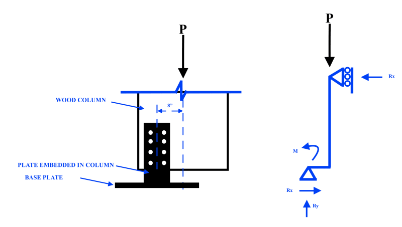
I'm an engineer in training and I'm trying to take a first pass at designing a column connection for a 36 inch deep by 18 inch wide by 20 ft tall wood column with a steel plate embedded in the middle of the column, bolted through on each side. The steel plate is welded to a base plate at the base (see attached sketch). The axial load in the column is 15 Kips and due to architectural reasons the plate embedded in the column is offset from the center of the column such that the center of the plate is 8 inches from the center of the column.
Could someone take a look at my attached sketch and tell me if I'm going down the right path? I think the bolts need to be designed to resolve the moment caused by the eccentric load but someone else has told me that the connection can be designed as a simple pin connection. with vertical and horizontal reactions... this doesn't make sense to me.
I think I need to design for shear in the bolts caused by the eccentric load. I would resolve this moment such that the top two bolts and the bottom two bolts provide horizontal reactions (equal and opposite direction) which is essentially a couple that resists the moment. This shear force would be equal to the (axial load * eccentricity)/vertical distance between the top and bottom rows of bolts.
I also think the eccentricity of the support also causes flexure of the column - the column needs to be designed for the moment caused by this eccentricity as well, right? And then isn't there also flexure of the plate as well?
If someone could tell me if I'm going down the right path that would be very helpful!