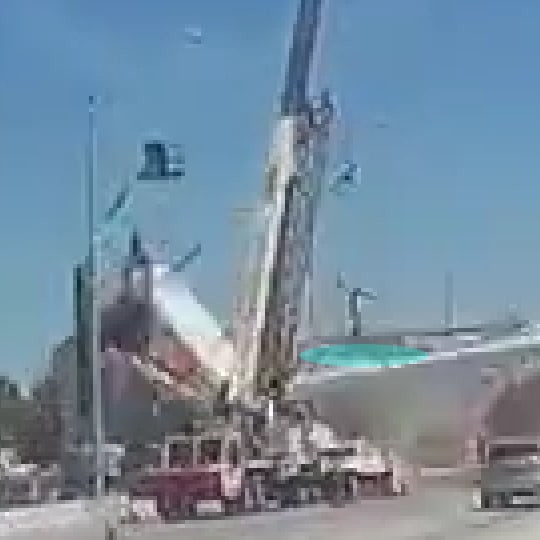
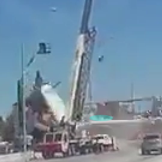
I prepared a cropped, enlarged version of the truck-cam video that is as free of artifacts as I can make it. A section of the
original video was cropped to 240x135, then I resized it by a factor of 400% to 960x540 using nearest neighbor interpolation, both operations done with native filters built into VirtualDub2. From what I've read, nearest neighbor interpolation doesn't introduce many artifacts because it simply moves pixels apart and inserts the value of the nearest neighbor. It enlarges an image while preserving the "chunky" nature of the original pixelated image.
I also created individual images for each frame in the cropped video, and they are named after the frame number in the original video - Frame0072.jpeg through Frame0086.jpeg. The JPEGs were saved at 100% quality.
I zipped the video and JPEGs into a single ZIP file that can be downloaded with this
Link. The video format is the ancient AVI windows format because that was all I could coax out of VD2. If someone asks I will convert it to MP4, but no guarantees on the quality.
My observations about the frames:
[ul]
[li]72-73-74 Nothing apparent[/li]
[li]75 - If you squint really hard and rub a magic nickle, you can just barely see the bottom of the deck move ever so slightly with respect to the traffic light beneath it. Collapse has begun. Or not. See the next frame.[/li]
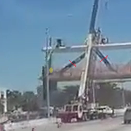
[li]76 - The deck and canopy are starting to drop, but member 11 does not appear to have moved much.[/li]
[li]77 - Member 11 still does not seem to have dropped or rotated much in comparison with the dropping of member 10 and the canopy.[/li]
[li]78 - Member 11 has started to move significantly. The canopy above member 12 has dropped slightly, so member 12 has been blown off the pier.[/li]
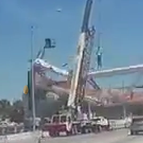
[li]79 - Member 12 and its attached canopy are in free-fall. The area around the 11-12 junction seems to be filled with debris, and the lower 20% of section 11 seems to have disintegrated.[/li]
[li]80 - The bottom of member 12 is plainly visible to the left of the pier, and the canopy attached to 12 has now dropped 3-4 feet, using the "falling man" for scale.[/li]
[li]81-82-83-84-85 - As the entire canopy continues to fall, the section attached firmly to member 12 causes it to rotate, and the bottom of 12 is pulled up and dragged onto the top of the pier.[/li]
[li]ADD: 82 - The north end of the deck is falling off the north pier. [/li]
[li]EDIT: 86 - The north end of the deck and the bottom of member 12 have reached their final resting places.[/li]
[li]
86 - The bottom of member 12 has reached it's final resting place.[/li]
[/ul]
ADD: Here are links to the
Whirled Gnus Playlists
And here is a link to all the
individual videos sorted by age, with newest first.