aniiben
Mechanical
- May 9, 2017
- 165
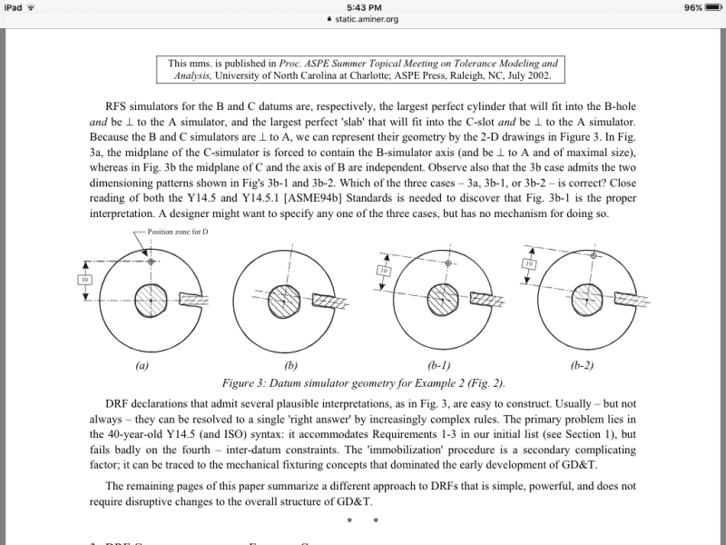
I have a dilemma: why 3b-1 is the correct interpretation?
Follow along with the video below to see how to install our site as a web app on your home screen.
Note: This feature may not be available in some browsers.
pmarc said:While the rule is true in cases where all datum features are planar, it does not always work that way. I am afraid Y14.5M-1994 doesn't address that
3DDave 7 Jan 19 20:21 said:the b-1 figure argument is carefully contrived to have an extra degree of control that is beyond being a tertiary datum control. b-1 depends on the tertiary datum being suitable, all alone, as a feature sufficient to provide reliable orientation control with minimal sensitivity for the part based on acceptable variations
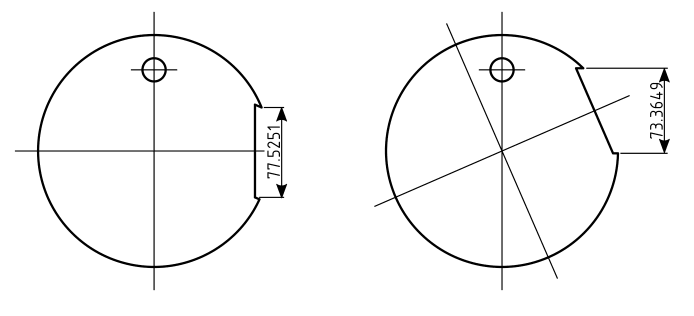
The "maximum contact with datum feature B" means that one has to try to bring the simulator B as close to the datum axis A as possible.