Jbingham1981
Industrial
Hi.. 1st time posting here and not an engineer by trade so I appreciate any help/guidance and will do my best to be clear.
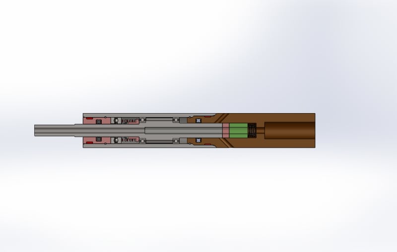
I have designed a small water rotational swivel. It is essentially a housing with a shaft through it. The shaft has 2 radial bearings on it. The housing is sealed on both ends. The inlet side of the swivel is larger than the outlet side on the OD of the shaft.
I intend to have the housing filled with hydraulic oil (type not yet determined) prior to being sealed.
During operation, the shaft inside will move forward because of the force of the water, with the smaller OD exiting the housing seal and more of the larger inlet side entering the housing. This should increase oil pressure, acting like a piston compressing the oil. Maybe I'm wrong about that?
My questions are these:
Is there a specific formula to calculate the oil pressure if the increase in shaft volume and oil type/weight/viscosity is known? I'd like to know that if I allow X amount of movement of the shaft (allowing a specific amount of shaft volume to enter the housing) it will correspond to ?? Oil pressure increase.
Am I correct in assuming that if I can increase the oil pressure inside of the housing to a force greater than the axial thrust forward on the shaft from the water, I will create some form of hydrodynamic bearing? Will the thrust of the water and the oil pressure find a "neutral" position at any point, eliminating axial thrust?
Any help on this is greatly appreciated.