Miami Pedestrian Bridge, Part II
(OP)
Site management has requested that we limit the length of the other thread by forming a new one. This subject may require III, IV....
Link to Part 1
Link to Part 1
RE: Miami Pedestrian Bridge, Part II
That triangle is the remaining parts of the members. The initial triangle is bigger.
RE: Miami Pedestrian Bridge, Part II
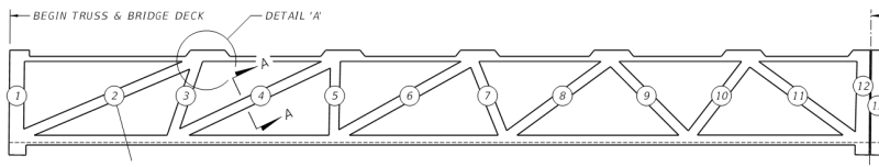
Can you points out these hinges in #10? #10 appears intact and aligned with its nodes until after collapse from what I can see. #11 deforms and loses alignment with the top node from the outset of collapse. My money is on the top of #11.
RE: Miami Pedestrian Bridge, Part II
Dik
RE: Miami Pedestrian Bridge, Part II
But from a liability perspective, if a state DOT looks at the plans prepared by the consultant, how much liability does he take on? Even though the state DOT is not likely not an expert in the structure being designed (and most bridge engineers aren't even familiar with ASCE 7 loading)...if a State DOT PE reviews the plans and then approves it...IMO he is taking on some liability with the structure.
Sorry...bit of a tangent :)
RE: Miami Pedestrian Bridge, Part II
I don't really know which node failed first. They were probably all failing. But in the dashcam video, both the top and bottom chord hinged at the ends of member 10.
RE: Miami Pedestrian Bridge, Part II
Not a tangent, but, the next phase... I'm surprised a lawsuit has not already been filed.
Moreso in the US, than in other parts of the world, the lawyer will use a 'scattergun' approach and name all parties. If the lawyer misses one that he should have included, he can be sued.
FDOT, the city, the University, the consultants, the constructor, and any of the sub-trades are fair targets...
Dik
RE: Miami Pedestrian Bridge, Part II
I couldn't tell if the failure was at the ends of the member or at the panel point the members framed in to. Could you?
Dik
RE: Miami Pedestrian Bridge, Part II
Well, targets certainly; 'fair' is debatable. Probably include the concrete testing lab, special inspectors, material suppliers, etc, to the list too.
RE: Miami Pedestrian Bridge, Part II
Can you post a screen grab of the phenomena you are talking about?
RE: Miami Pedestrian Bridge, Part II
The insurers would all be notified already, and are no doubt working out their respective positions regarding the inevitable claims.
RE: Miami Pedestrian Bridge, Part II
Just realised that I couldn't find any reference to confinement reinforcing in the anchorage zones... those high compressive loads from the post-tensioning would give rise to some high tensile stresses in the vicinity of the anchor.
Dik
RE: Miami Pedestrian Bridge, Part II
Yes the stresses would be fairly intense. The node region would be working real hard. I was wondering if the temporary rod was acting as confinement in some way, and when it broke or was released it led to the overall rupture.
RE: Miami Pedestrian Bridge, Part II
hokie66....I agree that hinges formed but it looks like those occurred first at the top of members 11/10, then at the bottom of 11 and then at the bottom of 10. But....sometimes hard to tell failure sequence in progressive collapses.
My best guess, and I assure you that's all it is, is that there was buckling or punching shear at the top of 11, rotational failure at the bottom of 11, then tension failure at the bottom of 10.
Issues such at these usually get solved by the numerous ideas posed in such conversation as we are all having. Hopefully these discussions will lead to someone reaching a logical conclusion of the failure, but as a group we don't have the benefit of the cumulative information from design and construction that will inevitably be forthcoming...either through determined analysis or the litigation process. The resolution of such failures is important to the future success of innovative design and construction, it's just unfortunate that such a high price had to be paid for this lesson.
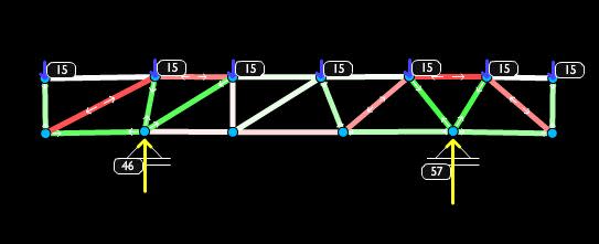
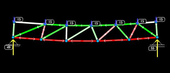
RE: Miami Pedestrian Bridge, Part II
A-In transit supported underneath in 2 places mid span
B-In Situ supported at either end of the span
These are not to scale or necessarily accurate, but give a general idea. Draw your own conclusions here.
RE: Miami Pedestrian Bridge, Part II
Concur... had lumped the others under sub-contractors... Wonder if VSL were involved with stressing the cables... They've been involved with post-tensioning for decades that I'm aware of, and are very good...
Shortly after it hit the ground...
Dik
RE: Miami Pedestrian Bridge, Part II
BA
RE: Miami Pedestrian Bridge, Part II
Your arrows are drawn to show the forces in the members and not the forces at the panel points; is that correct? Nice drawings...
And add to that the forces induced by the 'fake' cable stays, it gets more interesting. These additional forces should be included in the design for the blocks at the tensioning cable intersections.
Just because the cable stays are fake, doesn't mean they don't take load or influence forces in other members.
Dik
RE: Miami Pedestrian Bridge, Part II
I was just referring to the deflected shape of the truss as it fell. You posted it. Both the top and bottom chord kinked at the ends of Member 10. But I don't know where a failure first occurred.
RE: Miami Pedestrian Bridge, Part II
Yes, VSL (USA licensee is STRUCTURAL Group) did the supply, install and stressing of the PT - $440K subcontract sum.
Source: Link
And one of their field crew members died in the collapse - RIP.
RE: Miami Pedestrian Bridge, Part II
Dik
RE: Miami Pedestrian Bridge, Part II
Were you able to determine if the failure occurred at the ends of the web members or at the panel point?
Dik
RE: Miami Pedestrian Bridge, Part II
In reality, it has deep pockets and Florida probably has joint and several liability (haven't checked), so it will be drawn in and may pay up if the insurance of the real culprit doesn't.
RE: Miami Pedestrian Bridge, Part II
As to your question of Ron, what's the difference? The ends of the web members and the panel points are the same thing.
RE: Miami Pedestrian Bridge, Part II
If it were acting in compression, it would be aggravating the problem, I would think.
Dik
RE: Miami Pedestrian Bridge, Part II
A failure at the end of a member may be different than the panel point 'crushing' or 'exploding'.
Dik
RE: Miami Pedestrian Bridge, Part II
Hope they loaded it in the right places too, that truss arrangement has some significant load complexities.
RE: Miami Pedestrian Bridge, Part II
Dik
RE: Miami Pedestrian Bridge, Part II
This is the single biggest mystery to me.
RE: Miami Pedestrian Bridge, Part II
It seems to me that the I-beam shape of the bridge made it especially vulnerable to twisting loads and deformations, which could deteriorate the nodes of the web.
"Where the spirit does not work with the hand, there is no art." - Leonardo da Vinci
RE: Miami Pedestrian Bridge, Part II
It appears that hydraulic lines are leading to the box and there appears to be a pressure gauge attached to the box.
I'm betting that it is the hydraulic pump for the tensioning jack.
Bill
--------------------
"Why not the best?"
Jimmy Carter
RE: Miami Pedestrian Bridge, Part II
It's a larger member
RE: Miami Pedestrian Bridge, Part II
Yes, to achieve 'lift-off', whereby the coarse-thread nut "just" achieves 'daylight' from the bearing plate, the stressing load is a small increment above the pre-existing PT bar load.
For manual systems, usually the 'stressing stool' has an opening on one face enabling a technician to have a open wrench on the nut with a human-effort to verify that lift has been achieved (when the nut part-turns). Other systems use a displacement gauge to verify lift-off.
For more sophisticated systems, the stressing stool has a in-built, chain-driven wrench, however, the principle is the same.
Keep mind that the hyd pump operator is monitoring the applied force via gauge pressure. I have often used a load cell 'in-line' to verify applied loads with a bit more accuracy - especially true in proof or performance testing of rock/soil anchors.
RE: Miami Pedestrian Bridge, Part II
What I meant was, maybe that additional compressive load was stopping it from failing in some other way, as opposed to a compressive failure. There would be tensile stresses trying to leak out in all directions...
RE: Miami Pedestrian Bridge, Part II
Agree. The truss members have to stabilize the top.
RE: Miami Pedestrian Bridge, Part II
Yeah the top and bottom chord kinked, but it appears to be beyond the panel points. I can't see rotation of the ends of #10 or the respective panel points themselves. That's why I was asking...
RE: Miami Pedestrian Bridge, Part II
It appears it failed here first
RE: Miami Pedestrian Bridge, Part II
As an expansion, if the I beam was twisted at some point, would that stress the tendon anchorages in ways that would not normally be considered in the design process?
Cheers
Greg Locock
New here? Try reading these, they might help FAQ731-376: Eng-Tips.com Forum Policies http://eng-tips.com/market.cfm?
RE: Miami Pedestrian Bridge, Part II
There were some sets of top flange/canopy stabilizer cables installed at truss ends, and at transporter support points:
RE: Miami Pedestrian Bridge, Part II
Not a lot of detail/s on this, but there was a thickened end-diaphragm where the bottom chord PT terminates and where the diagonals intersect.
RE: Miami Pedestrian Bridge, Part II
I have a bit of experience with SPMTs. They are really a wonderfully designed piece of equipment, there are several manufacturers now but they all operate the same way. All of the axle lines during a normal transport are on the same hydraulic circuit which allows each axle to stroke up and down independent of adjacent axle lines while maintaining a constant bearing, so crossing normal bumps and slight elevation changes are no problem. But the axles only have 1ft of up/down stroke so there are limits. Also they talk about them in terms of the number of axles but there really are no axles, they have independent, two tire hubs on either side of an axle line.
And just because I think they are so cool, here's some more. Any hub can be isolated and raised, for instance if a tire blows out. They can turn the hubs on either side of the axle line independent from each other so you can walk the trailer nearly 90 deg from its long axis, or almost pivot in place, wonderful things.
RE: Miami Pedestrian Bridge, Part II
They were jacking a PT rod in a compression member because in order to de-tension it you have to actually increase the tension first? Isn't that just putting more compression force into a compression member? If,during post tensioning, you damage the member or the member's connection to the rest of the truss you're screwed because there isn't any redundancy. How many times have you heard of something getting "blown out" during a post tensioning job?
It seems to me it would take a pretty darn sophisticated structural model to account for the affect of all these post tension forces in addition to the forces in the truss to due self weight.
Build a steel truss, if you need extra weight use an oversized concrete deck. Sometimes stuff seems really cool on paper, but it sucks in real life.
RE: Miami Pedestrian Bridge, Part II
Re: The blue box.
Yes, you are correct. That has already been established in part I of this thread. Ingenuity even identified the manufacturer and model of the pump. He/she seems to have experience with it's use.
RE: Miami Pedestrian Bridge, Part II
http://www.wesh.com/article/orlando-based-attorney...
RE: Miami Pedestrian Bridge, Part II
and because of the length, they would also have to stabilise the unbalanced load from the bottom flange, too or at least a large portion of it.
Dik
RE: Miami Pedestrian Bridge, Part II
A lot of unknowns. It will be interesting to learn the details when they come out.
RE: Miami Pedestrian Bridge, Part II
And another showing spalling to underside of member #11 - the same side that the PT bar that was being stressed/de-stressed was located:
NTSB B-roll video here: Link
RE: Miami Pedestrian Bridge, Part II
Dik
RE: Miami Pedestrian Bridge, Part II
So there were two bars in #11? Not a central bar?
RE: Miami Pedestrian Bridge, Part II
The loads are additive.
RE: Miami Pedestrian Bridge, Part II
Nobody important (Computer)
That (rough) compression-tension FEA sketch is logical, and explains how the top members are in great compression across greater length/limited thickness elements = classic buckling failure at the odd-angled connections of each member that is in compression. But - Why would the "missing" center vertical temporary vertical pier NOT be installed?
Does the analysis/design team truly think that a cable-stayed bridge only needs the cable stays and central pier for "looks"?
RE: Miami Pedestrian Bridge, Part II
Thanks for the clarification... I seemed to recall from Lin's book that the precompression was 'absorbed' until it was exceeded by the axial load, was also thinking of preloaded A325 bolts not increasing in tensile stress until the preload was attained... never done work with prestressed compression members.
Dik
RE: Miami Pedestrian Bridge, Part II
BA
RE: Miami Pedestrian Bridge, Part II
When the load is equal to the prestressed load, what is the stress in the column?
Dik
RE: Miami Pedestrian Bridge, Part II
If the load is applied first, then the prestressing, the stress is 2P/A where P is the applied load.
If the prestressing is applied first, then the load, the stress is less than 2P/A but close to it.
BA
RE: Miami Pedestrian Bridge, Part II
...and then greater when they repull the rod.
RE: Miami Pedestrian Bridge, Part II
Correct, as per the attached photo:
RE: Miami Pedestrian Bridge, Part II
BA
RE: Miami Pedestrian Bridge, Part II
Munilla Construction Management (MCM), the South Miami-based firm that designed the FIU foot bridge, has been sued multiple times for unsafe practices in the past.
In early March MCM was sued by a construction worker who was severely injured when MCM’s “makeshift bridge” at Miami’s International Airport collapsed.
MCM is a Cuban-American, family-owned Miami company founded in 1983 that employs more than 1,000 people in several states. The company is a federal military contractor for the U.S. Army and Navy.
MCM was awarded the $14.2 million minority contract to design and build the cable-stayed bridge. The company is well-connected in Miami politics and it promotes inclusion and diversity in the workforce.
From their linked in reference
Employees at MCM | Munilla Construction Management
Melanie Rowan, P.E.
Senior Project Manager
Nelson Gomez Jr
Project Engineer
Maira Suarez
Alex Suarez
Senior Project Manager
Nelson Nunez
Fleet Manager
https://www.linkedin.com/company/mcm_3
RE: Miami Pedestrian Bridge, Part II
I thought it was FIGG who designed the bridge.
BA
RE: Miami Pedestrian Bridge, Part II
Is this not the likely culprit?
I know it's too soon to know, but:
- Say #11 was prestressed to resist the tension caused by the temporary transport load (the end of the truss was basically being hung by #11). No numbers here -- just call that Tension Force A.
- The bridge gets placed on the abutment. Load reversal city as the temporary supports get pulled away.
- Now say #11 is carrying 50% of the bridge self-weight in compression. And, at that steep angle. Call this Compressive Load B.
- Compressive Load B >> Tension Load A.
Wouldn't those PT rods go "slack" in that case?If so, wouldn't re-tightening them result in Compressive Load B +
TensionLoad A to occur at that node?That'd far exceed any other conceivable design load demand there, right?
"We shape our buildings, thereafter they shape us." -WSC
RE: Miami Pedestrian Bridge, Part II
The entire "truss" design was intended to transmit the visual and real loads from each cable stay down through the angled truss members to the lower bridge walkway. They could not be built and tensioned without assuming the load.
RE: Miami Pedestrian Bridge, Part II
Munilla Construction Management could be a sub-contractor to FIGG as prime, or the reverse: Put MCM as the "bidder" to the government/political people to get the minority preference (visible) contract, with the real work being done by the FIGG people. Or, the story I found could be dead wrong.
RE: Miami Pedestrian Bridge, Part II
No, because the rods are far more highly strained (i.e. stretched) than the amount the column shortens under the self weight loading. PT rods/strands stretch a lot.
You'd include all the loads in the design.
RE: Miami Pedestrian Bridge, Part II
This seems somewhat plausible. It is a rookie mistake all round but entirely plausible.
RE: Miami Pedestrian Bridge, Part II
...and that, along all the many more to follow, will have FIGG's attorneys and insurers issuing FIGG with a immediate cautionary notice (demand?) to talk to no one!
Source: Link
Speaking from past experience (a past project of remarkable similarity: bridge, post-tensioning, collapse, deaths...and its following lawsuits) these things get real ugly. The technical part of you wishes to assist the investigators, but you get 'muzzled' by the powers-that-be: i.e. lawyers/insurers/corporate/management.
RE: Miami Pedestrian Bridge, Part II
There has to be some other cause.
RE: Miami Pedestrian Bridge, Part II
A couple of 16 channel datalogger, a multiplexer, some software, and gauges etc, are readily affordable today, with very good reliability and ease-of-use.
Damn, it would have been a good research project for a select few FIU engineering students.
RE: Miami Pedestrian Bridge, Part II
Could still be an educational endeavour... Careful you don't do this...
Dik
RE: Miami Pedestrian Bridge, Part II
So if there is 20MPa compression in the concrete (about the maximum allowed at .5Fc), then the reduced tension in the prestress will be about 20 * 8 = 160MPa, so about 10% of the ultimate prestress force, or up to about 15% of the force after stressing.
RE: Miami Pedestrian Bridge, Part II
I think the idea is that it may have pushed an already deficient (or otherwise compromised) structure over the edge. The proverbial straw that broke the camel's back.
RE: Miami Pedestrian Bridge, Part II
Detail footage on member #11 from NTSB > https://youtu.be/aeJKqojmHgY?t=1m25s
RE: Miami Pedestrian Bridge, Part II
Exactly. What is pretty much clear is that the design and/or construction was defective. What is also almost certain is that the activities on the bridge by workers at the time were the trigger of the actual collapse.
My gut feeling is we are still largely talking about punching failure around the top connection. The cracking that was observed prior was likely this already happening. The works at the time was a supposed remedy. You have a thin top cord with high and concentrated punching loads from the web connections. It seems a fragile design to begin with. You want to get the reinforcing around those members done correctly.
RE: Miami Pedestrian Bridge, Part II
I think that is what I was saying! It was on the point of collapse at the time that the diagonal stressing (or it could have been destressing!) was being done.
The final straw may have been the works they were doing, but it should not have taken 1 straw to cause a collapse. In my experience a collapse normally requires bad design errors + bad construction errors + bad luck. Unfortunately they succeeded.
RE: Miami Pedestrian Bridge, Part II
BA did a quick back-of-the-envelope calc, above [in 'pagan' units] as follows:
About 23 MPa, in 'gods' units!
RE: Miami Pedestrian Bridge, Part II
The movement of 11 happens slightly after the the slab to the outside of the connection at 10/11 disintegrates on the 10 side.
RE: Miami Pedestrian Bridge, Part II
One of them looks still attached on deck.
RE: Miami Pedestrian Bridge, Part II
This is a 50m concrete structure supported at either end with very little useful stiffening to stop longitudinal deflection.
You have a handful of asymmetrical concrete trusses and 12 longitudinal tendons stopping the deck from wanting to deflect down and buckle.
Add to that any structural weirdness that may have occurred during transport. Did the main deck longitudinal tendons start to fail, we assume they were PT'd and grouted.
Maybe the strange behavior around #11 pulled the trigger, but by way the largest forces in the bridge is the main deck in tension.
Did something fail around #11 that had a significant effect on the main deck tendons, which were already on their way out?
If you take away the compressive force of the longitudinal tendons at one end, you get a very similar failure pattern that is seen in the dashcams
RE: Miami Pedestrian Bridge, Part II
The fallen deck is shattered, but continuous and it doesn't twist in a notable way on the way down, so it seems unlikely that the initial failure was due to the longitudinals. Since the deck is still tied together I expect the longitudinals are still continuous.
I don't know how much twist would happen if only one of the longitudinals near the center line failed, but it seems likely that there would have been a cascade of failure, again yielding either twist or separation.
Since there was no twist and the deck and canopy are still tied together without notable separations, the failure is somewhere else. The only other place is the truss-like members and their attachment to the deck and canopy.
RE: Miami Pedestrian Bridge, Part II
If you watch the video, there is a pronounced twisting of the upper deck as the truss fell.
Were the longitudinal tendons grouted? I thought not, someone said they were, but I am not sure.
RE: Miami Pedestrian Bridge, Part II
I would imagine the 2 cables to be detensioned would be in the top chord or "canopy" of the bridge since it would be a compression member once the span was set in place. Let's also not forget that the span had been in place for 5 days before it collapsed. I don't think what they were doing on Thursday was part of the design/construction sequence, it was a remedy for the cracking that had occured.
My hunch is the adjustment to the PT rod in member #11 had to do with the cracking that was found, and was the subject of the voicemail by the FIGG engineer to the FDOT engineer. They had a 2 hour meeting about the cracking a few hours before the collapse. Engineers for FIGG "delivered a technical presentation" about the crack. http://www.tampabay.com/news/FIU-Firm-had-meeting-...
The crack was on the north end and they were messing with the rod on the north end, I don't think that is a coincidence. Like others have said, the tensioning/detensioning action was probably the straw that broke the camel's back.
By now I'm sure there are people who know exactly what happened, but can't or won't talk because of legal fears and orders from their lawyers or employer.
RE: Miami Pedestrian Bridge, Part II
The cable stays, although decorative and not in place, would have an influence on the overall behaviour of the bridge. 8 - 1-1/2dia bolts (grade and anchorage unknown) would have a significant impact on load transfer. The stay, although on an angle, is in axial tension and has the axial stiffness of a steel member, whereas the bridge is concrete and in flexure.
Because they are above the shear center, they would also provide some stability.
Dik
RE: Miami Pedestrian Bridge, Part II
The stressing of #11 was due to cracking that was observed and was an attempt to fix an existing issue. And I do not believe they were destressing it, but were stressing the tendon...Though #11 may have caused the collapse...the collapse was due to a design failure of inadequate shear capacity.
Lets's assume Hokie's numbers are correct and that there is 1650K of compression in #11...Though we want to consider #11 with pinned ends..it is not..and is acting like a beam. The vertical shear at the bottom end of #11 would be about 950k...therefore Vu would have been about 1330k!...If f'c=6ksi...PhiVc would only be about 60k...there is not enough room in #11 (24"x21") to provide enough stirrups to handle the vertical shear in that member.
I believe that prior to failure #11 had some upward bending (concave up) and had cracking on the bottom side of #11. To address this, the engineer attempted to tighted the lower strand. The rupture first occurred at the bottom of #11..and with #11 removed..hinges were formed in the bottom of the slab near #10 and the top of the slab adjacent to #11.
When I step back and look at #11...It just doesn't not look big enough to handle the shear loads that would be imposed.
RE: Miami Pedestrian Bridge, Part II
I agree with your assessment. And you brought up another point which I had not thought of, namely that in addition to its poor performance in tension, the high E of concrete makes it a terrible material for use in a truss. Idealized trusses use pinned connections at the joints, steel trusses have enough flexibility (and redundancy in the material) that even though our nodes and connections are stiff, it still behaves mostly like an ideal truss. Concrete does not have that luxury, being such a rigid material it cannot accommodate the small rotations required at the points of intersection, and once it cracks it has lost all of its shear strength. If the design accounted for the shear strength of concrete + rebar (I'm making a leap here), when the PT rod let go and the member 11 lost the compression holding it together..........
Can someone who designs reinforced concrete please tell me how you typically design for shear in reinforced concrete?
Just Rebar or Concrete + Rebar?
RE: Miami Pedestrian Bridge, Part II
In the attached paper, the truss that was investigated had HS rods as verticals; they also pointed out the need for confinement reinforcement.
You can take that to the bank.
RE: Miami Pedestrian Bridge, Part II
If shear was indeed the failure then a sudden loss of compression in the member and/or any severe cracking would reduce a significant amount of the shear capacity of the member.
Professional Engineer (ME, NH, MA) Structural Engineer (IL)
American Concrete Industries
https://www.facebook.com/AmericanConcrete/
RE: Miami Pedestrian Bridge, Part II
the title of that article is "Truss-Girder"...that is not a truss but a beam with holes near the center where vert. shear is low. It is solid webbed as it approaches the reactions where vert. shear capacity is needed...We don't have that with this truss
RE: Miami Pedestrian Bridge, Part II
That makes little sense.
RE: Miami Pedestrian Bridge, Part II
Question for the more concrete experienced:
Is it possible that this extreme spalling on the under side of this member is indicative of a massive internal moment generated by near-instantaneous removal of one of the PT tendons and its associated compression load?
In other words:
-#11 starts out with 2 tendons which are apparently symmetrically placed about the beam's neutral axis
-Tendon A fails, leaving Tendon B intact and leaving an eccentric load in the member
-#11 is subjected to a giant internal moment and a bunch of material spalls off of the tension side
It also looks like there's a fair amount of steel inside those members beyond PT elements. Has no one found a reinforcement schedule yet?
RE: Miami Pedestrian Bridge, Part II
Dik
RE: Miami Pedestrian Bridge, Part II
The original procedure was that #11 tensioned rod was to be de-tensioned, once in place and was forgotten. A crack developed and reminded the contractor that #11 was to be de-tensioned because it was a major compression member and didn't need the prestress. In process of detentioning, coincidentally or due to a change in the loading regime; the collapse of the walkway was precipitated.
alternatively, if the stressing of the rod in #11 was increased and the rod failed, the sudden release of this energy may have caused vibrations that precipitated the collapse.
I still cannot wrap my ears around the 'fake' stays... If not intended, I would have designed a connection that allowed movement. It doesn't make sense that they had no purpose.
I did renovations to Polo Park shopping centre about 30 years ago... and when we were demolishing one of the small structures that had a huge sign connected to it, I discovered the 'connection' of the sign to the building was simply a pipe sleeved in a larger pipe. I talked to the engineer that did the original building and he explained that it was a city requirement that a sign of that size had to be attached to a building and he knew better than to attach a huge sign to a little building, so, he provided a slip connection that looked like an attachment.
Dik.
RE: Miami Pedestrian Bridge, Part II
Dik
RE: Miami Pedestrian Bridge, Part II
I think this means the lower member #11 PT bar did not fail because it would not be sufficiently anchored to act like a pull string and rip out the bottom of the beam.
RE: Miami Pedestrian Bridge, Part II
I don’t know how you go about designing those nodes. Strut and Tie? Probably not a lot of textbook examples for STM models resembling this situation. The fact that there are multiple bars in each truss diagonal makes it even more complex, as others have noted earlier.
You’ve got a highly stressed, determinate structure whose local behavior is complex and analyzed using a lower-bound method. If the mild steel around those nodes isn't sized and oriented just right...
I still can’t believe how fast this thing failed, though. From the video of the collapse, it almost looks like the bottom flange fails in tension. Maybe the nodal failure was at the support. Maybe the temporary PT in member 11 was helping confine the joint by adding a vertical clamping force across a horizontal plane just above the longitudinal PT anchorage. Think shear-friction design. The base of Member 11 simply shears across a horizontal plane and punche out the end of the structure. The problem with this theory is that the shear plane I'm thinking of is way too large.
RE: Miami Pedestrian Bridge, Part II
I have seen a lot of stuff go wrong. Today, everything is planned so that nothing breaks.
When I started, a lot of equipment was stressed to the breaking point.
You always asked yourself;
"If something breaks, where will it end up?"
"Don't be there!"
I always had a keen interest in the root causes of any jobsite failure as my future safety may depend on it.
Example, not a failure but an illustration;
We had a lot of anchor bolts to set in concrete for the structures of a substation.
The bolts were inserted into the holding templates and the nuts were spun on by hand to position the bolts vertically.
The templates were positioned on the forms and the concrete was poured.
A worker was tasked with removing the nuts in preparation to erecting the columns.
Why is it taking so long?
It only took half this long to place the nuts and the worker is only half finished.
When the concrete was poured, very small splashes of concrete were deposited on the threads of each bolt.
Now instead of spinning the nuts off by hand, there is just enough drag that each nut has to turned all the way off with a wrench. The worker was working hard but taking off now takes about 4 or 5 times as long as putting on.
What's the point?
The Florida crew has probably been installing the nuts for the most part by hand. They have probably done most of the post tensioning on this project.
It is possible that a spec of concrete or a grain of sand or other material became lodged in the threads and this nut could not be removed by hand.
I have seen too many crews that would keep increasing the tension trying to free the bolt to disregard this possibility.
If the excess tension pulled the anchor on the other end of the PT rod through the concrete, that may explain the failure of the strut and the spalling on the bottom of the strut.
This may not be the reason for the failure but it is too possible to be discounted offhand.
How about the concrete strength?
I have seen too many times concrete that did not meet the design strength. (Too much water makes it easier to work with.)
I have seen too many concrete samples that did not reflect the strength of the installed concrete. (Don't add the water until the inspector leaves with his sample.)
Stuff happens in the field.
Sometimes more stuff happens with design build projects.
Bill
--------------------
"Why not the best?"
Jimmy Carter
RE: Miami Pedestrian Bridge, Part II
Does this not induce a force which is essentially trying to push the top section to the right (North end) heaping even more misery on the no 11 support? (see Ingenuities diagram on 18 mar 20:55). Also this is where the initial collapse was focused, but may have been due to other issues.
I've read all the posts and watched the videos lots of times and the speed of collapse is just frightening and seems almost impossible to say what actually broke first.
Certainly fiddling about with the PT bars in that overworked no 11 strut was clearly not a good idea, but is this simply a flawed design from the get go?
Remember - More details = better answers
Also: If you get a response it's polite to respond to it.
RE: Miami Pedestrian Bridge, Part II
Once the bridge started deflecting, the angle of the compression member decreased , causing the load to further increase and cause collapse. Could be as simple as that.
RE: Miami Pedestrian Bridge, Part II
Dik
RE: Miami Pedestrian Bridge, Part II
cubits?
RE: Miami Pedestrian Bridge, Part II
It would have been so easy to take this bridge, lift it at the same locations and set it back down on the construction site with simulated pylons, perhaps only a few feet above the ground, and do actual load testing and so forth before placing it. They could have made multiple engineering class projects out of it; measuring deflection and comparing it to envelope calculations and sophisticated computer models over a couple of semesters before finally placing it. It's supposed to be in place 100 years; 8 months is very little to ask.
RE: Miami Pedestrian Bridge, Part II
BTW, does anyone know where KootK has been? I'd be interested in his perspective.
RE: Miami Pedestrian Bridge, Part II
Knowing him, he's likely read the whole thing.
Perhaps he's doing like I am and not guessing until we have more factual information? Not disparaging any for their current discussion; only that I personally prefer to wait until more information is available in things like this before I discuss it.
Professional Engineer (ME, NH, MA) Structural Engineer (IL)
American Concrete Industries
https://www.facebook.com/AmericanConcrete/
RE: Miami Pedestrian Bridge, Part II
Snopes says it is. I found this by Googling "florida bridge women". I Googled the title of the Sandra Rose article, and I found no web or blog sites that I know to be reliable.
I have corrected this to link to Snopes, as I originally intended. There is lots of anti-snopes stuff in the comments to the Sandra Rose blog. I observe that the post I was replying to has been deleted.
--
JHG
RE: Miami Pedestrian Bridge, Part II
I think this is correct. The reverse slope of diagonals 3 and (almost) 5 would have concentrated the compressive and bending stresses in the canopy towards the side of the bridge that failed.
It's possible/likely the asymmetric design of the truss, executed in service of making the bridge look like a cable-stayed structure, will prove to be an important factor in creating stresses the bridge design may not have fully anticipated.
RE: Miami Pedestrian Bridge, Part II
Like many people I suspect that's what it boils down to. Tensioning and snapping a bar in a compression strut shouldn't bring the thing down.
I'd put my money on #11 struggling and failure being triggered by the PT in some way or another.
We won't know for sure until we find out where the crack was and what exactly the guys were doing up there. It's a public enough disaster that I suspect we'll find out. At least I hope so.
RE: Miami Pedestrian Bridge, Part II
I find people get angry enough if you cost them a day.
RE: Miami Pedestrian Bridge, Part II
That's the strangest part of all this. The bridge was a intended to be fake. Decorative tower and cable stays?! What a bizarre concept.
RE: Miami Pedestrian Bridge, Part II
Yup, it gets stranger the more you think about it. What an odd series of design decisions when an actual cable-stayed structure would arguably have made a lot more sense. At the least it would have removed a hard-working concrete truss from the design.
RE: Miami Pedestrian Bridge, Part II
Speaking generally, the default mode of concrete joints is fixed while the default mode of steel joints is pinned. Each can be made to do the other, but only deliberately and with (sometimes) great effort. Meanwhile my statics textbook, with one of this firm's (or it's predecessor's) bridges on the cover, tells me that a truss has pinned joints, by definition. Someone forgot the basics.
RE: Miami Pedestrian Bridge, Part II
Even if it were designed by a woman, why would anyone in their right mind blame what happened on that. For shame on this well-respected forum.
RE: Miami Pedestrian Bridge, Part II
It is a fairly common concept across the world. It is a given for buildings and is common in bridges. I would almost suggest that a majority of pedestrian bridges have decorative features. Please lets not go back 50 years to purely function buildings devoid of character and life.
(Even in steelwork in industrial production we occasionally make some choices that are about looking nice rather than purely engineering. Only occasionally though mostly things are simply about function in my industry.)
[img https://c2.staticflickr.com/4/3138/3036688576_f65e...]
https://en.wikipedia.org/wiki/Bolte_Bridge
A simple concrete cantilever bridge which has fake towers simply to look more interesting.
RE: Miami Pedestrian Bridge, Part II
Yes, don’t get me wrong, I know decoration is common. Our Sydney Harbour bride for example has decorative pylons.
In this instance I’m taking about the actual structure itself. The structure itself - the member orientation etc - was designed as decorative adornment to the phoney towers and cables.
That’s completely different to when the architect sticks a couple of fins on the building.
RE: Miami Pedestrian Bridge, Part II
Forgetting the basics of pinned vs fixed seems surprisingly common in my observations. I'd hope it isn't common in bridge design but in more simple structure people seem to get lazy.
I was once involved in a construction where there were issues with columns bending on a simple single story structure. The structural engineer was blaming the fabrication/erection for it. I casually asked whether the column to beam joins were modeled as pinned connections to which the the engineer yes of course. I then pointed to the connection and asked does that look like a pinned connection to you? The columns were bending because the connection allowed significant moment transfer from the beam to the column.
RE: Miami Pedestrian Bridge, Part II
Question, was this concrete bridge cast monolithic, or are there some construction joints somewhere. I'm guessing each of the truss diagonals are individual members who's ends don't fit PERFECTLY together, maybe leaving small voids inviting crushing at the bearing points between members. Not sure about getting accurate calculation of shear across a construction joint either.
Also, I'm having a hard time believing an Engineer would CHOOSE to have the last diagonal in a concrete truss in compression, with a tendency to push it's way off the end if something failed.
Just watching.
LonnieP
RE: Miami Pedestrian Bridge, Part II
The top flange when exposed to bright sunlight will partially or fully shade the bottom flange and web members resulting in an average temperature gradient between the top flange and the bottom flange and web members. Because the web consists of concrete members the joints must be assumed to be fixed. The support of the entire bridge on the bottom of the section requires that all torsional stability is provided by the web members of the girder. This results in members that ultimately are subject to tension and compression plus biaxial bending based on rigid joints and extra stresses imposed by temperature differentials.
It is my opinion that the truss is much more like a beam than a truss mainly because from looking at the truss joints is does not appear to me that the streses from the tension and compression diagonals at the top or the bottom can be transferred directly to each other but require shear flow transfer to occur into the top and bottom flange. The top flange is hollow and I assume with diaphragms at the junction of truss diagonals. There does not appear to be any significant stirrup arrangement in the diaphragms or in the bottom slab so in effect it is then plain concrete in shear. The bottom flange is thin and wide and only a small fraction would be effective in transferring shear flow due to major shear lag effects in the bottom flange.
In summary I believe that the structure is much more complex than a "normal" truss but may have been designed as simply a truss and that the joint design was not suitable to transfer all of the loads between truss diagonals without complex stresses at the joints which were not designed to fully transfer the loads without involving substantial local effects on the top and bottom flange. Substantial shear stresses in the top and bottom chords and additional tensile and compressive stresses in the diagonals led to failure and with the maximum shear in the truss panel where member 11 lived due both to the end bearing reaction, culmination of any temperature gradients and maximum torsional stability stresses. This would also be the location of maximum shear flow if we look at the bridge as a girder where shear flow = Vq/I. The complexity which I believe is there plus the lower load factors taken for dead load do not allow in my opinion for making any simplifying assumptions.
Sorry for going on so long but for me to get this thing straight I need to logically go through this thing to conclude that it is an ill conceived design which is much too costly and in my opinion led to inevitable failure of the structure.
appster
RE: Miami Pedestrian Bridge, Part II
Check out Eng-Tips Forum's Policies here:
FAQ731-376: Eng-Tips.com Forum Policies
RE: Miami Pedestrian Bridge, Part II
Agreed, that is the location that I suggested. But I think the failure is actually a compression failure in the concrete in the slab at the connection. You have the very concentrated high compression stress in the concrete in the slab at the node from 9 combined with the precompression from the prestress tendons in the bottom slab that is also relatively high.
At the 3 - 4 frame in the video you see something like crushing in this area with an explosion of material upwards from the top (not as in caused by explosives). The diagonals still seem to be intact at this point. Next frame, the top drops very quickly and you get the rotations in the 10/11 node at the top that have been noted previously as the bottom slab at this location crumbles.
RE: Miami Pedestrian Bridge, Part II
If all is detailed correctly... that's what concrete is best at... compression is good.
Dik
RE: Miami Pedestrian Bridge, Part II
Those phoney cables are connected with 8 - 1-1/2"dia bolts (grade unknown) That could have a capacity of 400K or 500K. Not at all a slip connection.
Dik
RE: Miami Pedestrian Bridge, Part II
Even with the dreaded APPENDIX D!!!!!!!????? I'm not so sure but would have to plug it into Profis to see.
Check out Eng-Tips Forum's Policies here:
FAQ731-376: Eng-Tips.com Forum Policies
RE: Miami Pedestrian Bridge, Part II
http://www.figgbridge.com/FIU_Statement.html
https://heavy.com/news/2018/03/florida-internation...
https://heavy.com/news/2018/03/denney-denny-pate-f...
General Plan and Elevation
https://heavy.com/news/2018/03/munilla-constructio...
RE: Miami Pedestrian Bridge, Part II
Thank you very much for the detailed explanation, EPCI-Steel.
Additional questions about the tensioning process for anyone that may know:
1) Can the plastic flow of the steel, prior snapping, be seen in the gauge or be informed to the operator by some kind of alarm?
2) If so, does the hydraulic machine have any automatic device that prevents it from applying additional tension to the cable/tendon/tensioner beyond its yield point?
3) Can the machine fail in a way that excessive force is applied (failing switch, inaccurate gauge)?
"Where the spirit does not work with the hand, there is no art." - Leonardo da Vinci
RE: Miami Pedestrian Bridge, Part II
My money is on the top of #11.
RE: Miami Pedestrian Bridge, Part II
I don't know how anything is anchored or what grade the steel anchor is or if there is any confinement... the attachment is anything but a 'non-load' transferring connection, and, with this capacity, it has the potential for throwing a real wrench into the analysis of the walkway.
I've never used a 1-1/2 dia Kwikbolt...
Dik
RE: Miami Pedestrian Bridge, Part II
I don't know how this is undertaken contractually... whether a Certificate of Payment can be negated due to on site damage, or what. I've never encountered this. I don't know how to 'claw' back money once it has been released. I've withheld funds because work has been rejected (one of the few ways payment can be withheld, and, still honour the contract.
Dik
RE: Miami Pedestrian Bridge, Part II
It's likely that the rod failed at a thread; there would be little ductility or indication of failure before the rod 'broke'.
With yielding materials, hydraulic machines are very good for relaxing load and the load falls off quickly.
Yes, but the equipment is generally very reliable. The devices are robust and simple, and nothing can go wrong, go wrong, go wrong, go wrong, go wrong, go wrong, go wrong...
Dik
RE: Miami Pedestrian Bridge, Part II
No, really?
That would depend on the contract. But you're in a better position if the money's in your bank account than theirs. D&C probably helps too since it doesn't matter whether it was a design or a construction error, it all 'your' problem from the client's perspective.
RE: Miami Pedestrian Bridge, Part II
Nothing quite like Aussie sarcasm!
RE: Miami Pedestrian Bridge, Part II
To further Dik's replies to your questions.
I have used these type of hydraulic power units before to operate other devices, not a tensioning ram but other types of cylinders.
1) Can the plastic flow of the steel, prior snapping, be seen in the gauge or be informed to the operator by some kind of alarm?
No. These are very simple devices. The power pack consists of a pump, mounted onto a steel box which serves as a reservoir for the hydraulic fluid required, an inline pressure gauge, and a valve. The ones I have used are for operating a double acting cylinder so the valve has three positions, Open to line 1, closed, and open to line 2. One line will extend the cylinder, one line will retract the cylinder. If you want to derive useful force information, you must know the area of the piston where you are applying pressure (retraction is less because you must subtract the rod area) and multiply that by the hydraulic pressure from the gauge. From an untrained or inexperienced operator's perspective the only thing he will see once the steel is fully plastic is that the pressure on the gauge in not increasing.
2) If so, does the hydraulic machine have any automatic device that prevents it from applying additional tension to the cable/tendon/tensioner beyond its yield point?
No, the only limit is the ability of the pump to apply pressure and the individual components of the system. Usually the pump is the limting factor in the system and the cylinder is pressure rated to at least the pump pressure. 3000 and 10000 psi are the normal maximum operating pressures I have seen for these types of units.
3) Can the machine fail in a way that excessive force is applied (failing switch, inaccurate gauge)?
Everything can fail, in almost any conceivable combination, but a runaway pump scenario is very unlikely. Gauges can be inaccurate but they are supposed to be tested annually and given a certificate of calibration. Human error is much more likely.
RE: Miami Pedestrian Bridge, Part II
I can't see the position of the transporter wheels.
They have the ability to castor individually or be steered individually.
I doubt that the wheels would be dragging sideays.
Bill
--------------------
"Why not the best?"
Jimmy Carter
RE: Miami Pedestrian Bridge, Part II
At that cross section and length, how stable would that member be against buckling?
RE: Miami Pedestrian Bridge, Part II
Lonnie P asked if the truss/frame was monolithically cast. I think it was, more or less. There must have been some construction joints, but I don't think it was a matter of precast elements being connected together.
RE: Miami Pedestrian Bridge, Part II
The stressing equipment used on this project at the time of collapse was very simple in design and use. Basically a 10,000 psi MAX pressure hydraulic pump (electrically operated, with a wired remote), with a 4-way valve (controls fluid directional flow), a gauge, a set of hyd hoses that connect to a center-hole, double-acting ram/jack, that sat upon a big-a$$ stressing stool/chair whereby the 'stressor' can turn the nut.
This hyd design/setup is about 40 years old - tried-and-true. Simple.
Stressing equipment gets calibrated, typically every 6-12 months, and sometimes right before significant use. It is usually calibrated as a 'system' - the pump, jack, gauge - using a load-cell, and traceable back to NIST standards.
If you have a 200 ton jack setup on a 150 ton capacity PT bar, then it is possible to fail the bar during stressing. BUT this did not happen on this project. The PT bar did not undergo tensile failure.
The answer to all three of your questions is a general 'NO'.
There is equipment that is more sophisticated, and incorporates displacement gauges and in-line load cells, etc., but not particularly well suited to typical field operations.
A more specific answer to your question #3 is more to do with operator error (or stupidity?) than equipment malfunction. A hyd pump and a 4-way valve is very simple in operation. Provided the operator is trained and experienced in stressing, knows what the stressing force (gauge pressure) is, then seldom (very seldom) do bars get overstressed. There are also pressure relief valves on pumps and rams to avoid overload above 10,000 psi (700 bar).
Keep in mind that the 1-3/4" grade 150 ksi bar was stressed to 280 kips (max), about 70% of UTS. The bar has a ultimate tensile strength of 390 kips - so for an operator to go way beyond 280 kips - all the way close to 390 kips (40% more) - would take a huge screw-up.
RE: Miami Pedestrian Bridge, Part II
The distance between the canopy and the deck remains constant at #10, while outboard of #10 they both hinge together.
RE: Miami Pedestrian Bridge, Part II
I've never had a project that 'stopped' so abruptly... had a couple where the contractor went bankrupt and one where the contractor was terminated with questionable cause.
I would think that the contractor should be given the opportunity to make good, or, be sued for non-performance, but, I'm not sure. It gets real cloudy if you decide you no longer want the 'bridge'. Unless the contractor is terminated, he has every contractual right to complete the bridge (not likely he would).
As far as withholding the funds, there is a 'legal' out. Since the last draw, the work has been rejected for reasons... a legal contractual out. I occasionally have had clients that don't like something and want to withhold funds, and, pointed out contractually unless the work is rejected as non-compliant there is no easy manner of legally withholding funds. Contractually, it's usually black or white, with no allowance for grey.
Dik
RE: Miami Pedestrian Bridge, Part II
http://www.miamiherald.com/news/local/community/mi...
FDOT is trying to get out in front of this and distance themselves as much as possible. I haven't heard or read of anyone pointing any fingers at them.
Also interesting that FDOT says it didn't know of any "stress testing" (????) that was going on before the collapse.
"Over the weekend, FIU said the cracks were the subject of the two-hour Thursday meeting with FDOT, in which a FIGG engineer “concluded that there were no safety concerns and the crack did not compromise the structural integrity of the bridge,” according to a statement. FDOT then responded by saying its consultant who attended was acting in an administrative capacity only to ensure that the project was on time and still qualified for federal funds."
Really, the DOT sends a non engineer consultant to a meeting about a bridge being constructed over Florida SH-41? I know a little bit about a pedestrian bridge that was built over an interstate in the state where I live. The DOT here was all over every detail of the thing like stink on a pig's butt. Maybe hindsight is causing folks at FDOT to realize they should have exercised a bit more oversight over a bridge being built over one of their highways?
RE: Miami Pedestrian Bridge, Part II
Agreed... and, there could be criminal charges forthcoming, and how to prevent this from occurring again... something has to be learned from this terrible situation, but, someone is likely looking into how to 'wrap up' the project and what to do next. Was the bridge really necessary? will they construct another one? how are finances recovered? Lots of little unresolved questions.
Dik
RE: Miami Pedestrian Bridge, Part II
They can say what they want. That won't stop them from being included... he may have been party to the cause/harbinger of the failure and he was likely an engineer... and FDOT has money... It would be interesting to see what was presented at the meeting and see the minutes of that meeting if they had time to prepare them.
RE: Miami Pedestrian Bridge, Part II
Thanks to many here for their insightful comments. I have quoted a few of you in the story.
https://www.engineering.com/BIM/ArticleID/16670/A-...
Roopinder Tara
Director of Content
ENGINEERING.com
RE: Miami Pedestrian Bridge, Part II
Professional Engineer (ME, NH, MA) Structural Engineer (IL)
American Concrete Industries
https://www.facebook.com/AmericanConcrete/
RE: Miami Pedestrian Bridge, Part II
Professional Engineer (ME, NH, MA) Structural Engineer (IL)
American Concrete Industries
https://www.facebook.com/AmericanConcrete/
RE: Miami Pedestrian Bridge, Part II
Professional Engineer (ME, NH, MA) Structural Engineer (IL)
American Concrete Industries
https://www.facebook.com/AmericanConcrete/
RE: Miami Pedestrian Bridge, Part II
Thanks. I'm hoping we can get some idea of the joint detail that went into the frame before I start contributing to this discussion. I suspect we'll find that this bridge works more like a Vierendeel bridge than a truss bridge but between the angled web members, the post-tensioning, and all the unknowns I don't want to dive into it much further until we have more factual details. Just way too many things that could change whether this was a design error or not.
Professional Engineer (ME, NH, MA) Structural Engineer (IL)
American Concrete Industries
https://www.facebook.com/AmericanConcrete/
RE: Miami Pedestrian Bridge, Part II
1. This is a public forum. As such, it should be fair to quote anything posted here. Don't want to be quoted? Don't post.
2. Most participants aren't posting under their own name and those who do so have chosen to.
3. The title of this subforum is, "Engineering Failures and Disasters." If it shouldn't exist that subject should be discussed with the owners or moderators.
4. Would we all prefer that this discussion be left to the nonengineers?
5. There is far too much speech suppression in the world today as it is.
I suspect this post might earn me some ill-will but so be it.
RE: Miami Pedestrian Bridge, Part II
Congratulations hokie66.
RE: Miami Pedestrian Bridge, Part II
With a 'brittle' concrete structure, the analysis would have to include for the fixity at the panel points and reinforced accordingly. If a joint rotates and reinforcing is not provided, it will likely crack... it may not have any issue with overall strength, but, may have an adverse impact on esthetics.
Dik
RE: Miami Pedestrian Bridge, Part II
Interesting how FDOT is trying to distance themselves. It may not be that simple. Being a resource with money may make them a 'target'.
https://www.roadsbridges.com/fiu-broke-agreement-f...
I guess one has to ask the questions:
Were they aware the construction was on going?
Were they aware of the agreement/requirement with FIU?
Did they have anyone on staff visit the site during construction?
Why did they not intervene?
Dik
RE: Miami Pedestrian Bridge, Part II
On the contrary, nice summary. As I said before, I don't disparage anyone for commenting and discussing this failure. As you noted, I'm one of those people who chooses to attach identifiable information to my posts. This is part of the reason for my choice to not participate in the discussion yet. For those who post anonymously that's obviously not a concern.
In short, please keep discussing this; I just caution people keep in mind who may be reading it (public, media, etc.), I'm sure one or two FIGG engineers are watching this discussion and probably tearing their hair out that they can't join in and provide further details.
Professional Engineer (ME, NH, MA) Structural Engineer (IL)
American Concrete Industries
https://www.facebook.com/AmericanConcrete/
RE: Miami Pedestrian Bridge, Part II
Regardless, I read more and more often that the large tower, the cable-stayed members themselves (hollow 8 inch pipes ?) and their connection fittings (8 inch pipe flanges and bolts ?) and the cable-stayed connections into the angled truss members are "decorative. "
If so, then these "decorations" are directly to blame, are they not? The "truss" cannot be symmetrical because every truss inclined member must align visually to its matching cable-unstay diagonal member coming up from the bridge lower walkway. Unsymmetrical members equal greater stress in some member connections than others, but all connections need to be "visually" identical = some are overbuilt = too expensive, take too long to build properly.
Regardless of intent, the 8 inch pipes are very long, and will sag under gravity: This creates an elegant appearance when they are installed in a traditional suspension bridge, but an ugly distraction when hung basically sideways in this case. Thus, whether intended or not, the cable un-stays MUST be under tension to be visually straight under their natural gravity load at the extreme angles of their design,(and must be heavier (stronger) to resist that sag if NOT under their proper function as true cable stays. (A true cable stay cable will be straight BECAUSE) it is in tension holding the bridge up.) These decorative cable un-stays would need to be even heavier and thicker-walled to resist the inevitable bending (sagging and droop) than needed to be in "real tension" as a true cable stay.
Further, a true cable-stay holding the original lighter weight of the bridge if it were a true cable-stayed bridge, would be a smaller diameter, lighter cable: Holding "up" the canal side of the bridge, thrusting down on the tower and foundation, and holding "up" the traffic side of the bridge. The smaller diameter of a true cable under simple tension creates less hurricane wind force under live load conditions. 100-150-200 feet of 8 inch pipe at 20 to 23 pounds per foot = added dead weight on each connection point in each truss, rather than a simple true cable stay that is lifting the walkway at the same point.
The pipe (fake) cable un-stays are themselves heavy and have mass and wind resistance. As long round objects in the unpredictable gusty winds of a hurricane, this round shape creates a near-maximum turbulence and whipping load in a hurricane, and this extra load must be added to their gravity load under wind conditions = heavier, more expensive bridge = greater profits for the brddige design team, right?
So, regardless of claim as decorative devices, there are gravity loads, extra stress, and extra un-symmetric stresses added to each connection point of every member. Forget the cost and time of the claimed "decorative" tower and its cable un-stays: The tower itself and its cable un-stays add dead weight to the walkway, add hurricane wind loadings to the walkway at each connectino point, and create even worse cases of the very conditions a true cable-stayed bridge is intended to reduce and support.
RE: Miami Pedestrian Bridge, Part II
The bridge failed catastrophically under conditions of essentially "no load" (no foot traffic, no winds, no snow (obviously!) or rain, and with innocents underneath.
RE: Miami Pedestrian Bridge, Part II
Interesting. Hydraulic fastener stretchers are very common in manufacturing and typically require redundant load cells for reasonable accuracy and repeatability, a hydraulic pressure gauge isnt even included on many.
RE: Miami Pedestrian Bridge, Part II
Some of these items may not have improved living conditions... in addition, there may be other engineered products that have definitely harmed mankind. I tend not to be quite so smug about our accomplishments.
Dik
RE: Miami Pedestrian Bridge, Part II
To the structurals here, who hasn't, at the behest of an architect, worked their tail off to make something superflous work? Is that not part of our job? Ok, so the "cable stays" really aren't. So?
Any of us who has come into a project halfway through has had the thought, "This, this, and this look really strange and I hope that this, this and this were accounted for." Same situation here - we're all coming in after the fact and slowly learning what the design really is. I, for one, am willing to give Figg some slack here on all the design issues: the un-symmetry, the not-really cable stays, the non-redundancy, the kinda-a-truss but kinda-a-beam-with-holes issues. That firm isn't just 2 people in a garage somewhere. They have designed many, many bridges throughout the United States (including the I-35W replacement in Minneapolis).
Concerning the article title, to say that the design would have only "looked safe" is a tremendous extrapolation of the speculative comments here.
Maybe, when it's all said and done, we'll know one way of the other if the final design was safe (and maybe not if everything gets settled and everyone signs an NDA). Until then, all we're doing is throwing thoughts around. Yes, it failed, but there's only a couple hundred other factors that could have ultimately caused the collapse.
RE: Miami Pedestrian Bridge, Part II
what program would this be used in? I'm familiar with using ETABS although I assume this would be in SAP or some other program. (I'm a buildings structures guy). I ask because when modeling in ETABS and to a large extent in RISA as well, most FEA objects just end up being line objects that connect at specific points rather than an object that you can see how stress varies across the thickness of the section etc.
RE: Miami Pedestrian Bridge, Part II
In school if we got a 95/100 on an exam it was considered very good by most people (even the PE exam only requires a 70% to pass) but in the real world one miscalculation out of hundreds or thousands on a project can become a life and death issue. Very few professions require as much near perfection as ours. The fact that these types of tragedies are rare speaks well for our profession.
RE: Miami Pedestrian Bridge, Part II
Any of those programs you mentioned would be able to do it... About 45 years back, I wrote a 2D Frame Analysis program that would run in 64K and swapped in and out of a 5-1/4 disk... By adding a couple of joints within a foot or so of the panel point I could increase the stiffness of the 'short' member to provide a better model of fixity. Almost any frame program can treat the joints as fixed and will generate a moment at the member-panel point junction.
Dik
RE: Miami Pedestrian Bridge, Part II
Do not post any more in this thread.
thread815-436802: Miami Pedestrian Bridge, Part III