Continue to Site

Eng-Tips is the largest engineering community on the Internet

Intelligent Work Forums for Engineering Professionals

  • Congratulations waross on being selected by the Eng-Tips community for having the most helpful posts in the forums last week. Way to Go!

Wood Columns/Trusses to Steel Beam Connections

Status
Not open for further replies.

kmart30

Structural
Apr 28, 2016
183
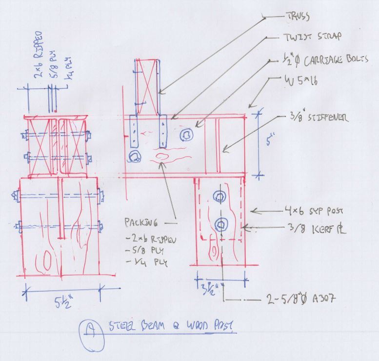
I have a few wood trusses bearing on a steel beam that is supported by wood posts. Everything is sized accordingly for gravity loads but I do have wind uplift loads from the trusses. Im trying to figure out the best and easiest (to construct) connections for the trusses and wood columns to the steel beam. I was thinking a combination of bolts, angles, plates, and maybe some welding but I would like to stay away from welds if possible. Any suggestions here?
 
 http://files.engineering.com/getfile.aspx?folder=82fe0642-6a3f-4c97-b917-5228e76604bc&file=2017-06-15_2049.png
Replies continue below

Recommended for you

my friend,
could be just me at the end of the day and a couple of beers,
but more info would certainly be helpful, and your attachment provided little in light of the connection conditions....., a sketch of the actual dimensional relationship between your " connections for the trusses and wood columns to the steel beam." would be helpful.
 
2x4 pre-engineered wood truss bearing on a steel W section; need an idea for an uplift connector. Also, steel I-beam bearing on a 4x6 SYP post; need a connection here to resit the uplift forces transferred from the trusses. Just looking for some general connection suggestions (loads are shown in the picture) but if you would like to design/draft up the whole thing I would gladly provide you with the all the necessary details and send a 12 pack of cold ones on the house....
 
Are the wind loads shown the uplift without factoring in dead load? If so it looks like you wouldn't have any net uplift and I would just use a 2-2x nailer bolted into the beam and attach the trusses with either toenails or a Simpson connector if you feel like it, the H2.5A is probably the most common. If those uplift loads are net uplift after factoring in dead load, 1.6k is pretty high so it might be better to use a Simpson column cap welded to the top of the steel beam, this is preferable to fabricated steel with bolts because the Simpson connectors use self driving screws and dont reduce the section depth of the truss chord, which will have a high tension load in it.

If it were me, if I'm using a steel beam I would just use some 3" pipe columns at each end and weld directly to the bottom of the beam. Another option would just be to go all wood with a glulam beam and attach the beam and column with a Simpson column cap with adequate uplift capacity, would also simplify the truss connections. If you really need to go steel/wood then I guess you could fabricate plates or angles onto the bottom of the beam and bolt into the column, you would need to place the bolts a minimum of 4 diameters from the top of the column for partial uplift capacity and 7 diameters for full uplift capacity.
 
Client wants the greatest ceiling height as possible which throws out an lvl beam. Every inch of clear height matters to him which is why I went with steel.

I'm not really sure on the uplifts if they are net or not; I'm grabbing these loads from old truss drawings with limited info. They do seem high but one of the trusses is a girder truss with a long length of jack trusses attached hence the high Gravity and uplift.

He is building this himself and has no construction experience at all; I heavily advised against this but he didn't care. This is why I am trying to avoid welding and anything else that would make it more difficult than it already is. I was thinking what you said about the bolts into columns but I will need to toss around some ideas for the trusses. Thanks for the advice dnlv!
 
I agree with dnlv, if a steel/wood combination is necessary due to client requests. bolting a nailer to the top of the steel beam would allow you to use standard connectors from a manufacturer to resist the uplift loads. For the column to beam fabricating an angle connection would be one of the easier routes. The connection doesn't have to be welded to the steel beam. depending of the loads a bolted connection could be designed for the steel beam to angle connection to the timber column.
 
If the loads are manageable (few hundred pounds), I'd consider drilling holes in the top flange of the W5 and using simpson truss screws (Strong-Drive SDWC TRUSS Screw). At the column, maybe it's as simple as a strap over the steel beam?
 
Great idea kipfoot! I spec out the truss screws all the time but obviously not with a steel beam. Sounds like I would need a washer for that screw? Thanks for the tips!
 
The scariest part is that the client is building it himself and has no construction experience at all.

BA
 
Yes this is scary but am I suppose to tell him I won't give him a design because he doesn't know what he is doing?
 
If you do take it on, be prepared to hold his hand throughout the construction process. And remember, he will not be inclined to take your advice; he has already demonstrated that.

BA
 
Another suggestion to him might be to order the whole frame prefabricated in the shop with the columns and base plates attached to eliminate field welding, and all he would have to do is drill and epoxy anchors. Can't say I feel great about the strap detail but u guess it's no worse than any typical wood to wood connection.
 
Given your situation, what I want most for your beam (and your DIY client) is that it not roll over at the ends. The proportions are already pretty good but I'd take it a bit further still. Some provisions for field tolerances are also prudent I think.

Capture_yn3iva.jpg


I like to debate structural engineering theory -- a lot. If I challenge you on something, know that I'm doing so because I respect your opinion enough to either change it or adopt it.
 
I like kootk's detail. I would add a note to put the hurricane stapping on opposing faces of the beam to avoid nailing conflicts in the truss and it will put your nailer bolts in double shear, increasing their capacity. Also make sure the proper edge distances for bolt holes are noted. Even framers with adequate experience often locate bolt holes too close to the edge of the member.
 
look at that sexy detail! Thank you for whipping that up kootk! This will definitely keep the beam from racking over and probably easier to install; it will make it easier if he gets the keys welded and bolt holes burned at the fabrication shop. We shall see what he says; his head might not stop spinning after this one...[ponder]
 
You're most welcome kmart30. My wife does a lot of wood structural and I showed her the detail for review last night. She liked it but said that she wouldn't be surprised if you got some push back on the kerf plate. She suggested end screwing the beam to the post but then I pointed out that the beam was only 5" deep and there likely wouldn't be space for the install of a vertical screw. In the light of day, I wonder if you might be able to provide aligned holes in both the top and bottom flanges of the beam and lag bolt down into the post that way with the lags passing through both flanges. Some folks don't like lags in end grain tension of course. I'd be okay with it in this application.

I like to debate structural engineering theory -- a lot. If I challenge you on something, know that I'm doing so because I respect your opinion enough to either change it or adopt it.
 
If KootK's detail will work for your situation, then might a simple Flitch beam accomplish the same objective? That would give the deflection limitation from the strength of the steel, along with the nailers on each side.
Dave

Thaidavid
 
Why a dropped steel beam if every clear inch matters to the owner? Upset a wood LVL beam in the truss space and use top chord intermediate bearing trusses. Or a flush LVL beam with hangers for bottom chord bearing trusses.
 
I thought about that putting an LVL in the truss space but if you were on site you would understand why that would not work.

Easier Steel Beam to 4x6 connection. Wrap Simpson CS14 coil straps over steel beam ends and nail straps to each side of 4x6 post. That came to me after all the great tips on this thread. Still tossing around the easiest steel beam to truss connection. I think the same straps might work just depends on how the truss chords are oriented at each truss bearing location.
 
kmart30 said:
Wrap Simpson CS14 coil straps over steel beam ends and nail straps to each side of 4x6 post.

Meh. I think that you'll always have some slack in that and that would make me wary of using it for rotational restraint of the beam end. Perhaps if the truss to beam connections can be considered to provide twisty restraint.

I like to debate structural engineering theory -- a lot. If I challenge you on something, know that I'm doing so because I respect your opinion enough to either change it or adopt it.
 
Status
Not open for further replies.

Part and Inventory Search

Sponsor