Continue to Site

Eng-Tips is the largest engineering community on the Internet

Intelligent Work Forums for Engineering Professionals

  • Congratulations cowski on being selected by the Eng-Tips community for having the most helpful posts in the forums last week. Way to Go!

Bolt tension due to moment about a ring of bolts 2

Status
Not open for further replies.

Polecat

Structural
Jul 7, 2000
132
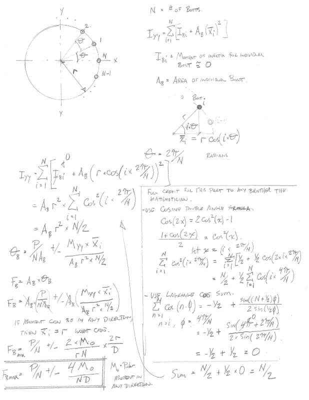
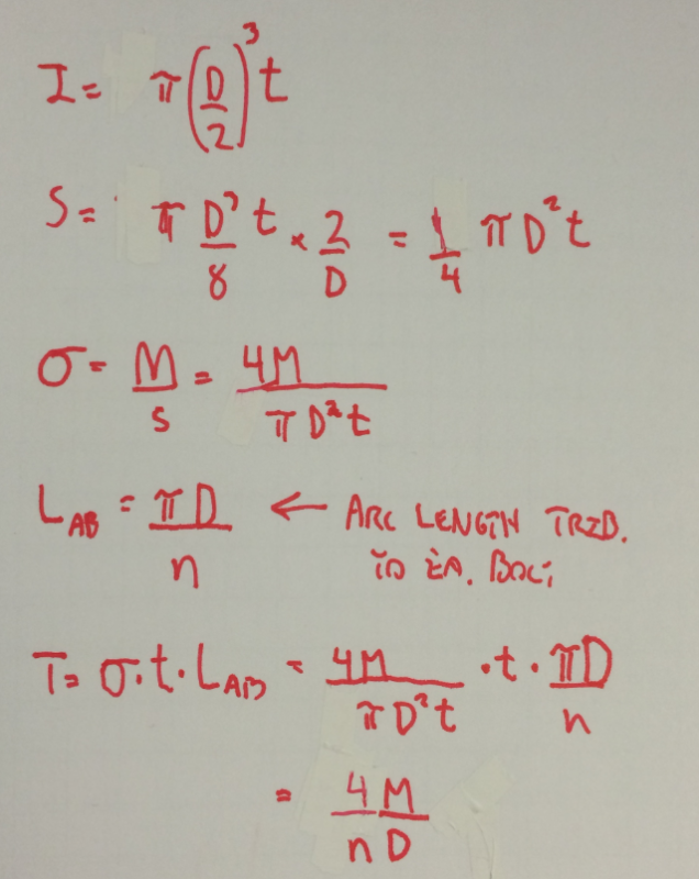
The TIA-222.G.3 standard says that the max tension on a single bolt (in a


baseplate attached to a pole) is calculated from the following formula:
1.02*pi*Mu/(n*Dbc) (assuming that there are at least 12 bolts and a minimal axial load is present)
Where:
Mu is the applied moment in inch-kips,
n is the number of bolts, and
Dbc is the bolt circle in inches

A dimensional analysis shows that the resulting answer is in kips of tension (or compression), but I cannot figure out how they derived the formula. TIA say that the bolt circle is treated like a ring of steel with a diameter equal to Dbc.

You can convert the total area of all the bolts into an equivalent area in a ring, and then calculate the section modulus of that hollow circle. Then you can do a M/S to get the max stress, which could then be applied to a single bolt to get its tension. However, I can't see where a formula that simply contains a pi/D ratio is anywere related to a section modulus.

Can anyone shed some light on this for me??


Replies continue below

Recommended for you

What do you get when you do it your way? It sounds to me like a reasonable approach.

BA
 
Ignoring individual bolt Ip's - Bolt Force, where N > 2 = P/N +/- 2 M / r N

Weird. Hate to miss out on some pi.

Ab = area of 1 bolt
theta = 2 pi / N
Ip = Sum(I=1 to N) {Ab x [r x cos(theta(I-1))]^2} = Ab x r^2 x N/2 (nice and clean); double check for an initial rotation of -theta/2
Sp = Ip/r

etc...

 
For thin ring, stress is Mc/I = MR/(pi*R^3*t) where t is the thickness of the ring.
That same stress applied to the whole area of the ring = 2*pi*R*t*MR/(pi*R^3*t) = 2M/R
Divide by 12 to get 1/12 of that and 2M/R/N or 4M/D/N.
So I get a 4 factor instead of 1.02pi. This is the approach normally used for tanks and codified in the tank standards.

Alternatively, assume a thin ring fully yielded. Centroid of one half of the area is 2R/pi = D/pi.
Moment is M = N/2*P *D/pi*2 = NPD/pi and P = M*pi/N/D.
If you apply a 1.2 factor in there, you'd get 1.2M*pi/N/D. Are you sure that's 1.02 and not 1.2?
 
I use standard formula 4*M / (n*dbc)
I believe its from asce petrochemical bolt design.
Seems 25% more conservative than tia. Maybe they include some sort of redistribution?(since only cca 1 bolt gets the maximum tension load)
 
I get the same as Kiltor which is pretty close to the OP estimate.

OP said:
assuming ...a minimal axial load is present)

Could this explain the discrepancy? Does TIA elaborate on that?

Capture_nl9o42.png


I like to debate structural engineering theory -- a lot. If I challenge you on something, know that I'm doing so because I respect your opinion enough to either change it or adopt it.
 
Many thanks to all of you for your quick and informative responses.
I appreciate the insights, especially from KootK's derivation (By hand, yet! I like that).
That shed some light on where many of those formulas originated.

Mucho Gracias [thanks2]

 
I recently looked at a similar problem but took a different approach than KootK's theoretical one.

I set up a spreadsheet where I could input the number of bolts, OTM, and diameter.
The spreadsheet assumes that all bolts will take the same load in T or C, figures out the angle between, how far they are from the centroid, and the figures out that the load per bolt should be.

Comparing the spreadsheet forces to the 4M/nd equation, the equation typically predicts ~25% higher loads than the spreadsheet. They predict the same force when you have a moment applied at 45 degrees to 4 bolts, such that you have one bolt each in T/C. In every other circumstance, the equation indicates a higher load so it's quick, easy, and conservative to use.

Comparing the spreadsheet forces to the TIA equation and 12 bolts min, there is much less error. I looked quickly and 12-20 bolts, and the TIA equation ranges from 0%-3% higher than the spreadsheet forces.
I'd say that if you have 12 bolts or more, this equation is quick, easy, conservative, and gives a more accurate answer than the 4M/nd equation.

I`d be happy to share the spreadsheet if anyone is interested.
 
Yes, ONCE20036, I would be very interested in seeing the spreadsheet.
Would you be so kind as to provide a link from which it can be downloaded?
Thank you.

 
KootK, are you representing t for bolt circle thickness?
 
Leftwow said:
KootK, are you representing t for bolt circle thickness?

Yeah. That hypothetical ring of steel needs to have some thickness ant "t" is it. It cancels out anyhow so all is right with the world regardless.

In the world of Excel and Mathcad, I'd just solve this in a manner similar to Teguci's method. Treat each bolt like a point area like we do with pile groups under moment. Then write an algorithm to rote the circle in one degree increments and report the maximum result. Is is precision overkill? You bet. Would that stop me? Hells no.


I like to debate structural engineering theory -- a lot. If I challenge you on something, know that I'm doing so because I respect your opinion enough to either change it or adopt it.
 
You calculate the maximum bolt tension/compression by using M*c/I ± P/n. The big question is how to calculate I of the bolt group since your moment can be in any direction due to the nature of the loading (wind & seismic). It turns that if you have "n" bolts evenly spread (equal angles between bolts) out over a circle around a center point, the moment of inertia (ΣIg + ΣA*d^2) of the bolt group does not change as you rotate the bolt group. You can confirm this by using ACAD and using the massprop feature to find the moment of inertia.

Someone smarter than I was able to figure out a simple formula for this case of a bolt circle evenly spread.

I = n*((D/2)^2/4+BC^2/8) [Units are (unit)^2]

n = # of bolts
D = Bolt diameter
BC = Diameter of the bolt circle
 
The maximum force on a bolt (ignoring individual bolt moment of inertia's) due to overturning moment in a bolt circle (at least 3 bolts) is Fb max = 4 M / N D. No Pi, and no other factors. If you want to consider axial load (why wouldn't you?) Fbmax = P/N +/- 4 M / N D.

Here's a proof I put together. I had to call in the heavy for sorting out the Cosine summation but the rest is engineering 101.

bolt_circle_l6wzdf.jpg


I'd say the TIA formula is wrong. They should use the actual calculated force and then introduce applicable load and phi factors and not use an imaginary Pi factor.
 
EngineerEIT - I`m not much into long math equations these days, but I disagree with your conclusion. The T/C reactions in a set of four bolts is very different if you apply the loads parallel to a side or at 45 degrees to a side.

Teguci - I`m not much into long math equations these days, but I disagree with your conclusion. Similar to EngineerEIT, how do you account for the fact that the rotation does matter?
I would agree that TIA is technically wrong, but offer that it's damn close. Close enough I'd say. How else could you offer a simple solution that can be used in less than a minute and offers a reasonable solution to a huge number of potential configurations? (12 bolts at 10' diameter vs 15 bolts at 30' diameter vs 40 bolts at 20' diameter)

Can anyone offer insight into how I can share an excel spreadsheet?
If anyone wants to email me at anotherskait @ yahoo dot com, I'd be happy to share that way.
 
@Once20036 I never said that the force in the bolts doesn't change as you rotate the angle of the bolt group. The moment of inertia of the bolt group doesn't change as you rotate the bolt group but the distance to the extreme "fiber" AKA c in the Mc/I equation does change as you rotate the bolt group. Teguci's solution gives the maximum force when the distance "c" is equal to the radius of the bolt circle. The Mc/I methodology is a more general solution which will work for other values of "c". Generally one is concerned with finding the maximum force seen by the bolt group.
 
Makes sense, thanks.
So is your/Teguci's methodology assuming a linear distribution of forces in the anchor group? Such that the force in the anchor bolt varies with our distance off the centroid?

My methodology assumes that every anchor bolt gets the same force. This means that there is some stretch in the steel and some load redistribution.

 
Thankfully, a plastic hinge at the base of a non-redundant column is outside of my design experience.
 
Revised the spreadsheet to also calculate based on a linear force distribution and there's a good match to your equations - Teguci & EngineerEIT

So the fundamental difference is assumed distribution of forces. Is it a uniform assumption for LRFD loads and a linear assumption for ASD?
Is one assumption better than the other regardless of load factors?
 
Status
Not open for further replies.

Part and Inventory Search

Sponsor