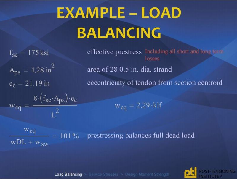
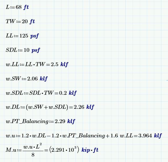
Existing Post tension beam doesn't meet what the existing loads would require
(OP)
I have an existing structure I'm analyzing and I'm just not matching something. It's a parking deck, live load = 40 psf. Beam is 20" wide x 26" deep, pan joist system is 6" side x 18" deep with 4" slab (6" x 14" + 4" slab). The Beam span is 57' and the tributary width is 28'. The effective prestress force is 350 kips. At the center of the beam positive auxiliary rebar consists of 2#5 and 2#6 bars. At the support negative auxiliary rebar consists of 3#7 and 2#8 bars. I'm getting a capacity of 712 k-ft positive and 872 k-ft negative. I am getting a DEMAND of 630 k-ft positive and 1262 k-ft negative. This can't be right. I'm just checking the existing loads, I haven't put the proposed loads or anything on there. d=23.75". I'm not sure what I'm missing, I may be burnt out and missing something to simple that I may be booted from the forum but any help would be greatly appreciated.
RE: Existing Post tension beam doesn't meet what the existing loads would require
I like to debate structural engineering theory -- a lot. If I challenge you on something, know that I'm doing so because I respect your opinion enough to either change it or adopt it.
RE: Existing Post tension beam doesn't meet what the existing loads would require
I like to debate structural engineering theory -- a lot. If I challenge you on something, know that I'm doing so because I respect your opinion enough to either change it or adopt it.
RE: Existing Post tension beam doesn't meet what the existing loads would require
Are you assuming wL2/24 for M+ and wL2/12 for M-?
Doible check your effective prestress of 350 kips (or 14 x 1/2" dia tendons).
Assuming this is an internal span, with maximum drape (h = 21.5"), the equivalent balanced load is approx 1.54 klf [from P x h = wL2bal / 8 ]
Assuming a pan joist spacing of 30", your equivalent slab thickness is 6.8" over the trib width, so including the SW of the 26" x 20" beam the total applied SW is approx 2.75 klf.
Only load balancing 56% of SW which is low...so maybe recheck your Peff from the existing design or shop drawings.
Of course, if my assumption of the pan joist spacing of 30" is wrong, so too is my calculated balanced load
RE: Existing Post tension beam doesn't meet what the existing loads would require
@Hokie/IDS: Your statements imply that there was something inaccurate or misleading in mine. And I dispute that. I believe that you're simply viewing things from what I have come to see as the "Aussie perspective" on PT design. And that is likely influenced by the prevalent use of bonded PT in your area.
From a design perspective, one can consider the benefit of PT drape in at least two ways:
1) As an internal action improving sectional resistance or;
2) As an external action balancing the applied loads (Link).
Either way, PT drape absolutely does alter the moment Demand/Capacity situation. As such, it's entirely plausible that one -- particularly a north american -- might have neglected to include the benefit of PT drape along with potentially eccentric pre-compression.
I like to debate structural engineering theory -- a lot. If I challenge you on something, know that I'm doing so because I respect your opinion enough to either change it or adopt it.
RE: Existing Post tension beam doesn't meet what the existing loads would require
The ultimate strength only depended on the f'c, the fy of the reinforcement, the locations and areas of strands and mild rebar, and the overall geometry of the beam itself.
The demand (required moment capacity) did get affected by the secondary moments in continuous members due to the prestress force and strand location. Maybe that's what KootK is referring to.
Check out Eng-Tips Forum's Policies here:
FAQ731-376: Eng-Tips.com Forum Policies
RE: Existing Post tension beam doesn't meet what the existing loads would require
Certainly, that is one way to think of it. I wouldn't consider the effect secondary, however, as I'm used to that term being associated with the less significant hyperstatic effects.
All I really stated initially is that PT drape helps resists load and should be accounted for in some fashion, which is obvious. Otherwise, we wouldn't have the Golden Gate Bridge to admire. Whether you view the effect as an externally applied balancing load, or a boost to ultimate member capacity, is immaterial and simply a matter of choice.
I like to debate structural engineering theory -- a lot. If I challenge you on something, know that I'm doing so because I respect your opinion enough to either change it or adopt it.
RE: Existing Post tension beam doesn't meet what the existing loads would require
I like to debate structural engineering theory -- a lot. If I challenge you on something, know that I'm doing so because I respect your opinion enough to either change it or adopt it.
RE: Existing Post tension beam doesn't meet what the existing loads would require
The ultimate strength at a given section depends only on the reinforcement (of both kinds), its location, and the concrete. Whether it is draped or not does not affect the ultimate flexural strength.
RE: Existing Post tension beam doesn't meet what the existing loads would require
If anyone ever gets a chance to view his PT class from UCLA, you will not be disappointed. His commentary on the confusing shear provisions in the code and secondary effects in indeterminate systems alone makes it worthwhile. His father, Ken, is a "Teacher's Assistant" so you get good info from people that have been doing it for over 60 years combined.
RE: Existing Post tension beam doesn't meet what the existing loads would require
Not so fast. I believe that w_0p represents the effective balancing load and would in fact be negative. I've KootK-ized the example below to show how PT drape effects the bottom line when it comes to bending capacity/demand. I think that you'll get the idea.
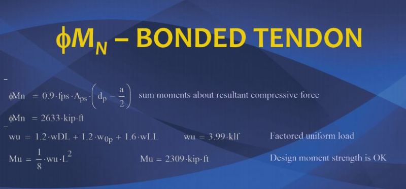
I like to debate structural engineering theory -- a lot. If I challenge you on something, know that I'm doing so because I respect your opinion enough to either change it or adopt it.
RE: Existing Post tension beam doesn't meet what the existing loads would require
Whether or not it is draped affects the ultimate external load carrying capacity. Surely, you're not disputing that?
When I think of unbonded PT, the sketch below pops into my head verbatim.
M_external_load - M_balancing < M_ultimate
OR
M_external_load < M_ultimate + M_balancing
I like to debate structural engineering theory -- a lot. If I challenge you on something, know that I'm doing so because I respect your opinion enough to either change it or adopt it.
RE: Existing Post tension beam doesn't meet what the existing loads would require
Wrong.
The uplift effect of the tendons is NOT included in the ultimate strength checks, nor is it included in the crack section checks. Only the Secondary (parasitic) prestress is included at ultimate as others have suggested. And this does not only happen in the Southern Hemisphere, it happens in the Northern Hemisphere as well.
It is only included in uncracked section checks because people think of it as a total prestress moment. It can be separated there as well. Two versions shown below.
The full prestress effect is P.e + Msec = Mp at any point.
When you are doing uncracked section checks
stress = P/A + M/Z where
M = Mdl + Mll + Mp = Mdl + Mll + P.e + Msec
You could also write this as
stress - P.e/z = P/A + M/Z where
M = Mdl + Mll + Mp = Mdl + Mll + Msec
Where P.e is your load balancing effect.
The second version is consistent with how it is done for crack section checks and ultimate strength calculations where the P.e effect is regarded as part of the capacity and NOT part of the applied loading.
If you look at cracked section checks under any condition from transfer to ultimate strength, P.e is actually part of your resisting capacity. If you also include it as part of the applied loading, you are counting it twice.
PS If you want a good book on PT I would be looking at Collins and Mitchell or RI Gilbert books, or go back to the earlier writers, Leonhardt or Guyon. Apparently the book mentioned above does not even recognise that deflections need to be calculated (2nd hand as I have not read it myself)!
RE: Existing Post tension beam doesn't meet what the existing loads would require
P.e is not the load balancing effect. The load balancing effect is a result of the angular change in tendon profile (Your Msec?)
AND
I'm not treating P.e a part of the applied load rapt. I'm treating the effect of tendon angular change as part of the applied load as discussed in that PTI document that we've been passing around and as illustrated in the sketch that I posted with my last comment.
Checks, checks, checks... The simple fact of the matter is that tendon drape helps to resist load. Whether that assistance is conceptualized as an external action reducing demand, or as an internal action increasing capacity, is simply a matter of choice and convenience. Since most designers are interested in the ability to carry load external to the concrete, I find it convenient to take the view that tendon drape increases capacity.
Here's a question for you: if tendon drape does not improve a pre-stressed member's ability to resist load, then why do we bother with it?
I like to debate structural engineering theory -- a lot. If I challenge you on something, know that I'm doing so because I respect your opinion enough to either change it or adopt it.
RE: Existing Post tension beam doesn't meet what the existing loads would require
The draped strand member would have greater load resisting capacity than the straight strand member in real terms. We simply choose to ignore that improvement in our ultimate strength checks. Some examples where we do include tendon drape in ultimate strength checks would include:
1) Suspension bridges
2) Wood/concrete beams reinforced with external PT.
Conceptually, these are the same.
I like to debate structural engineering theory -- a lot. If I challenge you on something, know that I'm doing so because I respect your opinion enough to either change it or adopt it.
RE: Existing Post tension beam doesn't meet what the existing loads would require
Just for the record, I hope I can sometimes be ingenious, but I am not Ingenuity.
Doug Jenkins
Interactive Design Services
http://newtonexcelbach.wordpress.com/
RE: Existing Post tension beam doesn't meet what the existing loads would require
So, I take it that you have accepted that ultimate strength computations are not affected by drape, at least in the context of prestressed concrete?
RE: Existing Post tension beam doesn't meet what the existing loads would require
Kootk,
It has nothing to do with bonded/unbonded prestress. The only difference with unbonded is that there is no strain/compatibility between the prestressing steel and the concrete surrounding it, so everyone tries to guess the stress in the unbonded steel at ultimate as it is not directly related to the strain in the concrete.
To look at the simplest case of a simply supported span (just to take continuity effects out of it), to balance a load of w, the moment at mid span from the load balancing would be
mp = wl^2 / 8
The prestress force to balance this is mp / e = P
so P = wl^2 / 8 e
or P e = wl^2/8
So the moment effect of load balancing = P.e
This is true at any point in ant determinate member. In indeterminate members, secondary moment effects change this but the overall logic is still the same. In indeterminate members, the secondary moment effect is considered to be an external action, while the P e (balancing effect) is considered to be part of the capacity.
I sincerely hope you have not designed any PT members by this methodology as they will be under capacity by P e, so could be reaching their true ultimate capacity at or below the service moment.
RE: Existing Post tension beam doesn't meet what the existing loads would require
If you look at the Leonhardt (No he was not Australian) bible on PT, written well before TY Lin discussed load balancing, he was talking about Equivalent Moments from prestress and relating them to the Moment diagram in a span. He was basically talking about Moment Balancing, later popularized by Lin into Load Balancing. Problem with Load Balancing is that the logic only works easily in simple cases and where there is no change in the prestress force in a span. Moment Balancing is much easier to work with and it is related to P.e at every point in the span. For a parabolic tendon that comes out to a balanced load over the length of the parabola. Whew you start adding reverse curves in your tendons, straight lengths, harped profiles and transmission lengths in pre-tensioned strands and post tensioned dead ends, then load balancing is near impossible to work with.
To answer you last question
"if tendon drape does not improve a pre-stressed member's ability to resist load, then why do we bother with it?"
For several reasons,
Continuous members would require double prestress, straight top and bottom without it, so would have twice as much prestress. And most buildings have continuous members!
It is convenient for calculation, especially in the old days when we hade to do moment distribution by hand to get the moments and shears!
It provides a prestress resisting effect that is simple for quick comparisons with UDL loading.
It raises the anchorages from the bottom at the ends to give cover to the anchorage and to provide sufficient concrete to resist bursting stresses.
It reduces the likelihood of transfer stress problems at anchorages where there is no SW moment to act against the prestress moments induced there by straight tendons in the bottom, as is often experienced in pre-tensioned members and results in some strands with unbonded lengths and sometimes compression face strands.
When Lin first suggest the Load Balancing logic, people liked the idea of being able to get a "flat" floor. Unfortunately, it was only flat under one load case at one instance in time, so was really useless, but the logic was used for a long time.
Interestingly, you can reduce your deflections in a simply supported span by using a straight tendon in the bottom if you could anchor it and put up with any transfer stress problems caused by it. And the same in a cantilever with a straight tendon in the top, again if you can anchor it
RE: Existing Post tension beam doesn't meet what the existing loads would require
I might look in this evening and see if I have anything to add.
Doug Jenkins
Interactive Design Services
http://newtonexcelbach.wordpress.com/
RE: Existing Post tension beam doesn't meet what the existing loads would require
He may be a bit abrasive at times, but I don't believe it is in your best interest to tell rapt to go away. He lives and breathes this structural specialty, and his advice is invariably good...and free.
RE: Existing Post tension beam doesn't meet what the existing loads would require
A few of my comments on the book:
1. Very USA-centric re design and practices.
2. No mention of deflections. Not one word. All member sizes in the examples are selected from L/D ratios and no follow up check on long-term deflections, nor any mention about cantilever deflections.
3. Whilst there are many example calculations, there is too much reference, in my opinion, to PT Data, the authors software for designing PT floor systems.
4. Interesting that there are photos in the book of UCLA students doing line dancing! That is a first. I guess if TY Lin can author a Shakespeare parody in his 1963 book, a photo of line dancing is "acceptable" too.
5. The book is expensive - like US$150 for a paperback. But, full disclosure, I am a tight-arse and buy lots of $4 books at Thriftbooks.com
6. There are a good number of practical worked examples.
7. Great collection of photos from project sites - including the good, bad and the ugly (tendon ruptures, etc).
Time will tell re Ken's comments:
RE: Existing Post tension beam doesn't meet what the existing loads would require
Now that we have all 'hijacked' your thread...here is some on-topic info:
1. With the pan joist spacing of 6' c/c, the prestress is balancing about 70% of DL to interior spans, but less in end spans.
2. Based upon a quick check I ran, you require significant more flexural reinf, as you indicated. Calcs based up 14x0.5" UNbonded strands, or 350 kips.
3. There are ductility problems in negative moments regions adjacent to interior columns, requiring compression reinf.
4. Long-term delfections are up there.
Factored Moment and Shear: (all spans loaded, no LL reduction):
Mild Steel reinf required, for end span:
Deflection estimates:
RE: Existing Post tension beam doesn't meet what the existing loads would require
Is rapt the raptsoftware guy or is that just a coincidence? I'm glad I'm on this thread. Learning something from the guys I usually just lurk on. Hopefully I can start contributing to the forum soon.
RE: Existing Post tension beam doesn't meet what the existing loads would require
@rapt I have sent a request for demo and pricing on your product. I'm talking to our supervisor about purchasing a software so hopefully we'll hear from you all soon.
RE: Existing Post tension beam doesn't meet what the existing loads would require
1) @jplay: I believe myself to have been fundamentally incorrect with regard to the advice that I supplied above. Please disregard all of it save that sexy example problem that I provided. I considered continuing this conversation in a separate thread of my own so as not to hijack but, in the end, I decided to carry on here. The thread seems to have wrapped up and I figured that you would enjoy the ensuing technical debate/discussion/gong show. Let me know if I'm wrong about that.
2) @rapt: I regret and apologize for my outburst the other day. Things around here work best when we check our egos and pride at the door. I slipped up and let my lizard brain run amok.
3) No one needs to fear for any of the post-tensioned slabs and transfer beams that I have designed in the past. All of that work occurred some time ago when I used to actually perform the detailed design of things. Back then, I used the same equations, examples, and software as everyone else and, consequently, came up with similar results. Frankly, I believe that I'm a much better engineer now as I question many fundamental things that I previously took for granted in the interest of productivity. From time to time, as now, that results in my having to admit some errors in my thinking.
4) I own pretty much all of the important books on pre-stressed concrete. And I've flipped through most of them, at least briefly, in the last 96 hours. None of them seems to present the information that I seek in quite the way that I need it presented. No doubt it's out there; I just haven't been able to find it in the time that I have available. Consequently, I'm going to attempt to derive the relevant aspects of PT behavior myself, from first principles. And I hope that folks here will critique the material that I present in order to help me get things sorted. Please be kind. Being wrong is an opportunity without equal but, nonetheless, it's painful.
5) No doubt, the things that I'll be "discovering" will be things that you think are obvious and things you may have already told me above. Don't think that I haven't been listening. I have. Sometimes it just takes sketches and a particular presentation in order for me to undo my own long held engineering dogma.
I like to debate structural engineering theory -- a lot. If I challenge you on something, know that I'm doing so because I respect your opinion enough to either change it or adopt it.
RE: Existing Post tension beam doesn't meet what the existing loads would require
I like to debate structural engineering theory -- a lot. If I challenge you on something, know that I'm doing so because I respect your opinion enough to either change it or adopt it.
RE: Existing Post tension beam doesn't meet what the existing loads would require
In detail B below, I've examined the equilibrium of the concrete without the PT tendon and, importantly, without the compression block reaction at the section cut. Because the forces that the tendon impose on the concrete are the inverse of those imposed by the concrete on the tendon, I again take the moment summation about point O to be zero. I propose this as non-rigorous proof (to myself) that balancing forces and anchorage reactions form a self-equibrilating system that, taken in concert, do nothing to improve bending capacity. I also offer this as one explanation for the following statement made by hokie:
In detail C, I again study the concrete on its own, this time with the compression block reaction included. I come up with the usual ultimate moment capacity formulation. This is the part that I have trouble feeling with the usual presentation (my previous post). Looked at in isolation for an unbonded system, there's no tendon tension force on the concrete at point O.
I like to debate structural engineering theory -- a lot. If I challenge you on something, know that I'm doing so because I respect your opinion enough to either change it or adopt it.
RE: Existing Post tension beam doesn't meet what the existing loads would require
Yes. Previously, I mentioned the example of the Golden Gate bridge. I thought that a salient example at the time. In order to get my world view fully adjusted, I feel it necessary to answer my own questions regarding that example. What was missing there, I think, was
a) a proper appreciation of the self-equilibrating nature of Pe & Balancing loads and;
b) Recognition that the PT anchorage situation is markedly different for the golden gate bridge.
To clarify, I've sketched up:
a) A fictional version of the Golden Gate that is more like a PT beam, where drape doesn't matter and;
b) A fictional version of a PT beam that is more like the Golden gate bride, where drape matters.
I like to debate structural engineering theory -- a lot. If I challenge you on something, know that I'm doing so because I respect your opinion enough to either change it or adopt it.
RE: Existing Post tension beam doesn't meet what the existing loads would require
That is true at midspan, but the flat strand provides greater ultimate capacity at every other point in the span than the draped strand.
It should also be noted that the flat strand provides greater camber than a draped strand with the same maximum effective depth.
BA
RE: Existing Post tension beam doesn't meet what the existing loads would require
Load balancing effects are present in the ultimate condition and affect the ultimate strength that we count on. However, those load balancing effects are perfectly offset by the the moments generated by the anchorage forces acting on the member. The net effect on ultimate load carrying capacity is that there is no effect at all.
My original, flawed, assumption was that load balancing effects were assisting with load resistance in the ultimate state but were ignored as matter of choice / conservatism. Statements like those shown below have contributed to my misunderstanding. They make somewhat more sense to me now that my understanding has evolved some.
You see variations of this a lot in the literature. Load balancing effects are used to resist load in the ultimate state. They're just offset by other effects. Our procedures for calculating ultimate bending capacity account for all that but, unfortunately for me, do not make that accounting transparent. So, really, the salient point in the above statement should really be to not account for the load balancing effects twice (rapt's point somewhere above.
Again, this statement gives me the false impression that load balancing effects represent a capacity improvement that has been deliberately left on the table. Perhaps it's a matter of terminology that's resulted in my confusion with with this one.
I like to debate structural engineering theory -- a lot. If I challenge you on something, know that I'm doing so because I respect your opinion enough to either change it or adopt it.
RE: Existing Post tension beam doesn't meet what the existing loads would require
1) You reviewed my diatribe and agree with every scrap of it or;
2) You noticed that I noticed that I was wrong and you're happy to leave it at that?
I'm hoping that it's the former.
I just stepped ofo of my elliptical machine and realized that I'm screwed again. If Pe moments offset load balancing effect moments at all locations, then there's no net curvature change and therefore no "lift" in the slab. And that can't be right.
Really, I'm just getting started. I suspect that there's much more ground to be covered once I try to extend these same principles to continuous members.
I like to debate structural engineering theory -- a lot. If I challenge you on something, know that I'm doing so because I respect your opinion enough to either change it or adopt it.
RE: Existing Post tension beam doesn't meet what the existing loads would require
BA
RE: Existing Post tension beam doesn't meet what the existing loads would require
I like to debate structural engineering theory -- a lot. If I challenge you on something, know that I'm doing so because I respect your opinion enough to either change it or adopt it.
RE: Existing Post tension beam doesn't meet what the existing loads would require
Upon further consideration, moments due to Pe and balancing effects only cancel out when moments are taken about the tendon axis. For other locations, like the section centroid, balancing loads effects will remain uncancelled and impacting curvature so as to generate lift.
I like to debate structural engineering theory -- a lot. If I challenge you on something, know that I'm doing so because I respect your opinion enough to either change it or adopt it.
RE: Existing Post tension beam doesn't meet what the existing loads would require
A tendon draped in a parabolic curve, when stressed, will exert a uniform uplift on the concrete member. That is what T.Y. Lin meant by load balancing. One difference between a prestressed tendon and a freely suspended cable is that the tendon relies on the member to supply the horizontal reaction whereas the cable relies on external reactions.
If the concrete starts to crush at midspan, the stress in the tendon can no longer be sustained and the member fails. That is why load balancing cannot contribute to ultimate load.
BA
RE: Existing Post tension beam doesn't meet what the existing loads would require
No argument there. That's kinda where I started.
Just like my Golden Gate bridge sketches above, right?
This may sound odd given my recent difficulties but I disagree. You know... tepidly.
Per the sketch that I posted above, and have repeated below, I believe that the balanced load effects are implicitly built into our procedure for ultimate moment capacity. If you removed the load balancing effects, ultimate bending capacity would need to be reduced as a as result.
Logically, if concrete crushing meant that we could no longer rely on the tension in the tendon, all that we'd be left with for moment capacity would be the portion attributed to the non-prestressed reinforcement. And that certainly isn't reflected in our procedure for determining ultimate flexural capacity.
I like to debate structural engineering theory -- a lot. If I challenge you on something, know that I'm doing so because I respect your opinion enough to either change it or adopt it.
RE: Existing Post tension beam doesn't meet what the existing loads would require
If the tendons are flat, i.e. without drape, at the same effective depth as you show at midspan, the prestress force would then be applying an equal and opposite moment at each end of the member, namely P.e which would cause an upward deflection of PeL/8EI; if you call that load balancing, then the load it is balancing is a uniform moment across the span without external reactions, not a gravity load balancing.
If the tendons are flat at the neutral axis, there would be no balancing of any kind but the ultimate moment capacity would still be the ultimate tendon force times the depth to the middle of the stress block.
BA
RE: Existing Post tension beam doesn't meet what the existing loads would require
1) With no tendon curvature, the transverse balancing load effect would be non-existent and thus it would create no moment about point O.
2) The horizontal anchorage force would also create no moment about point O because the anchorage and point O would be vertically aligned.
3) The vertical anchorage force would be zero and thus also create no moment about point O.
4) All summed, we again have a self-equilibrated M=0 system in which the net effect of the balanced load forces and anchorage forces on ultimate moment is no effect at all. And, if that's correct, it would be great as a universally applicable principle is the most confidence inspiring kind in my opinion.
I like to debate structural engineering theory -- a lot. If I challenge you on something, know that I'm doing so because I respect your opinion enough to either change it or adopt it.
RE: Existing Post tension beam doesn't meet what the existing loads would require
The procedure for determining ultimate moment capacity in a prestressed member is identical to that of a conventionally reinforced member and has nothing to do with balanced load effects.
Why would ultimate bending capacity need to be reduced if the load balancing effects were removed? Can you provide an example of that?
BA
RE: Existing Post tension beam doesn't meet what the existing loads would require
The procedure does not involve balanced load effects but that's only because they cancel out. The mechanism by which ultimate loads are resisted does involve balanced load effects, however, per my derivation.
To see the effect, take my detail C above and remove the balanced load effect. To maintain equilibrium, the moment resistance would decrease by the amount that the balanced load effect previously contributed to the system.
No, because it's not possible. That was the 'proof' that I proposed with details A and B. The balancing effects and anchorage forces form a self-equilibrating system that has no net effect on ultimate moment capacity. I'm not suggesting that we need to change our method for calculating ultimate flexural capacity. I'm simply clarifying that a) our procedure assumes that balancing forces are alive and kicking in the ultimate condition b) load balancing forces are in fact alive and kicking in the ultimate condition.
You're preaching to the choir. And nobody's posted more graphical supporting material here than me. All of my latest arguments have been predicated on my derivation (A/B/C) being correct. It was my hope that it would be more fruitful for folks to debate the validity of that underlying, graphical derivation rather than debate the consequences of that derivation. I really am trying to reduce extraneous wordsmithing.
I like to debate structural engineering theory -- a lot. If I challenge you on something, know that I'm doing so because I respect your opinion enough to either change it or adopt it.
RE: Existing Post tension beam doesn't meet what the existing loads would require
VSL Slabs
VSL Buildings
VSL Foundations
VSL Detailing
I like to debate structural engineering theory -- a lot. If I challenge you on something, know that I'm doing so because I respect your opinion enough to either change it or adopt it.
RE: Existing Post tension beam doesn't meet what the existing loads would require
We all have bad days!
Prestressing by itself creates a self-equilibrating stress state. In a weightless member, the centroid of the prestress force (tension) will be the same as the centroid of the compression force in the concrete at any point along the member and in a determinate member, that will be at e from the centroid where e is the tendon eccentricity from the concrete centroid. Thus there is no "lever arm" between the compression and tension forces. For an indeterminate member, it will be offset from e by Msec / P.
The concept of "balanced load" is simply a method of visualizing and calculating the effects of the change in tendon curvature. Yes, it induces a curvature in the member, equivalent to the moment from the balanced load = wl^2/8 and this is exactly equal to P.e. They are simply 2 methods of calculating the same thing. In some texts they are not called balanced loads, they are called Equivalent Loads (eg Gilberts book) which is less misleading! Leonhardt, while developing the formula for an upward load u = V 8 f / L^2 for the calculation of prestressing effects does not even give it a name as far as I can tell, just suggesting that it makes the calculation of the prestressing effects much more simple than calculating the eccentricities of a parabolic tendon.
For complicated cable profiles and where the Prestress force varies significantly, calculating P.e and using curvatures to calculate the secondary prestress effects is a lot easier as there may not be a logical balanced load profile.
Once you have the theoretical weightless system with P and C at the same height, as you then add load, the compression zone changes and its centroid moves away from the pure prestress position creating a lever arm. As more and more load is added, it eventually cracks the concrete (assumed 0 tensile strength for crack control and ultimate calculations) and the compression centroid moves up further increasing the lever arm even more. At the same time the force in the tendon is increasing due to either strain compatibility for bonded PT or due to the elongation of the whole tendon for unbonded. So you have an increasing P and an increasing lever arm as you continue to add load. Eventually it gets to the ultimate condition and you have the maximum stress you are going to get in the tendons (and any other reinforcement) and the maximum lever arm possible and this gives you your ultimate strength.
RE: Existing Post tension beam doesn't meet what the existing loads would require
As far as the raw facts go, I agree with all of your last post. It is consistent with, and is a natural extension of, the derivation that I presented above (details A/B/C). What I still disagree with, somewhat, is the perspective taken. Everything that follows will be stated with unbonded PT in mind, to the extent that does or doesn't matter.
To me, this implies that Pxe is the real physical phenomenon and balanced load effects are a convenient construct for "visualizing and calculating the effects of the change in tendon curvature". I believe that it's the other way round: the balanced load effect is really and truly applying transverse load to the member, in service and at ultimate, and it is Pxe that is the convenient construct for visualization and calculation.
At the ends of a member, the center of compression starts off at the anchorages. The physical action that shifts the center of compression to coincide with the tendons as we move along the length of a member is the balancing load effect. That's what gets it done as it were.
At the start of this thread, I was trying to double dip with regard to the balancing load. And that was wrongheaded. However, I still find statements to the effect of "balancing loads have nothing to do with ultimate flexural capacity" to be rather misleading. I believe that what people really mean, or should mean, when they make such statements, is:
1) Our standard calculation procedure does not explicitly include balancing load effects and/or;
2) Balancing load effects should be included once in the formulation, not twice.
Were it not for the balancing load effects, when we calculated ultimate flexural capacity of a member, the post-tensioning force would have to be located at the elevation of the anchorages rather than at the elevation of the tendon. Viewed in that sense, the balancing load effects have a significant impact on ultimate flexural capacity.
I like to debate structural engineering theory -- a lot. If I challenge you on something, know that I'm doing so because I respect your opinion enough to either change it or adopt it.
RE: Existing Post tension beam doesn't meet what the existing loads would require
Just trying to make sure I understand what you are suggesting, so I will go through what I think your steps are
If we assume a single determinate span of length L and a rectangular section of depth D with the prestress force P anchored at mid depth. And then the tendon drapes down by the amount e parabolically to midspan from each end.
Assume the compression centroid depth at ultimate is dc and prestress force increases by deltaP at ultimate to be P + deltaP.
We will forget about capacity factors etc at this stage, assume they are 1 for ease of calculation.
balanced load = wp = 8 P e / L^2
1 Calacuate capacity at end of span at the anchorage
M*anch = (P + deltaP) * (D/2 - dc) (basically Tension force * lever arm)
2 Calculate capacity at midspan
M*midspan = M*anch + wp l^2 / 8
Is this what you are suggesting?
RE: Existing Post tension beam doesn't meet what the existing loads would require
What you've presented is a simplified, alternate formulation of ultimate flexural capacity wherein the balancing load effect IS considered explicitly, correct? If so, then yes, it would be a salient example of the point that I've been trying to make.
I've been trying to come up with a version of this myself but was unsure of some aspects of it.
I would describe this formulation as the ultimate capacity calculated from the view of the prestressing effects as external loads. I do recognize that it's not as computationally expedient as the usual formulation of course. And I'm not proposing it as a replacement, just an illustrative example.
I like to debate structural engineering theory -- a lot. If I challenge you on something, know that I'm doing so because I respect your opinion enough to either change it or adopt it.
RE: Existing Post tension beam doesn't meet what the existing loads would require
KootK,
It is not just me stating this, Bondy and Allred state it explicitly on page 72 of their 2nd edition PT book "Post-Tensioned Concrete - Principles and Practice":
RE: Existing Post tension beam doesn't meet what the existing loads would require
I know. Similar statements pervade the literature. It wasn't my intention to single yours out.
I like to debate structural engineering theory -- a lot. If I challenge you on something, know that I'm doing so because I respect your opinion enough to either change it or adopt it.
RE: Existing Post tension beam doesn't meet what the existing loads would require
What is the source of this reference that you quote above:
RE: Existing Post tension beam doesn't meet what the existing loads would require
I like to debate structural engineering theory -- a lot. If I challenge you on something, know that I'm doing so because I respect your opinion enough to either change it or adopt it.
RE: Existing Post tension beam doesn't meet what the existing loads would require
Google tells me that it was from the first of the four VSL papers KootK linked above :)
Surprisingly, an exact search on Google finds a couple of other (possibly dodgy) sites with that paper, but not the VSL site.
Doug Jenkins
Interactive Design Services
http://newtonexcelbach.wordpress.com/
RE: Existing Post tension beam doesn't meet what the existing loads would require
The first paper is from the ACI Journal from 1985, authored by Waller and Zimmerman.
The second file is a discussion of the authors paper by Ken Bondy and Prof Mattock questioning the authors logic.
Evidently the authors original paper was not peer-reviewed before it was published!
RE: Existing Post tension beam doesn't meet what the existing loads would require
The attached in the authors paper. The file attached in the post above is the discussion.
RE: Existing Post tension beam doesn't meet what the existing loads would require
Authors paper it attached...hopefully.
RE: Existing Post tension beam doesn't meet what the existing loads would require
Don't start suggesting that my post in any way justifies your logic. I was asking if that was what you were suggesting, not suggesting that it was a logical solution. I do not consider this to be a logical solution to ultimate strength calculations of PT members.
I think your position and the logic I asked about above shows complete lack of understanding of prestressed concrete analysis and design concepts.
Looking at the same example at midspan and using the same variables and simplified logic in it, and considering it as a strain compatibility exercise (except for the force in unbonded PT tendons)
M*midspan = (P + deltaP) * (e + D/2 - dc) (basically Tension force * lever arm)
This applies at any cross-section in the member and in any member, no matter how complex the section shape, the tendon profile and everything else.
If you break that down, there is a term in the right side which is P . e which is the initial PT contribution to the ultimate strength. But you cannot substitute Mp in there because in an indeterminate member, Mp includes secondary prestress as well, it is not just P.e . Also, there is a deltaP . e term that is completely missed in the earlier logic. THis increase in the prestress force also occurs in unbonded tendons but to a lesser degree due to the lack of strain compatibility. You could substitute Mp - Msec for P.e but why would you want to, as that Mp - Msec = P.e.
But this method allows the designer to calculate curvatures, strain compatibility between materials (other than unbonded PT), ductility effects etc. It is a logical way to estimate the ultimate capacity (or any) of a PT cross-section and also the moment curvature relationship throughout the loading range of a PT cross-section, from transfer to ultimate capacity. Something that is very useful for deflection calculations of cracked PT members.
To take this one step further, in the deflection calculations in RAPT, a service condition check, the balanced load and its effects are not used as they cannot be used in a cracked section check. It is all based on curvatures and curvatures are based on moment/curvature relationships, something you cannot do using your logic.
Even in Ingenuity's post above which suggests that it illustrates very well the effects of the service state, I would qualify to consider only the hypothetical/uncracked service state. It gives not assistance in crack control calculations or deflection calculations, both of which are Service State.
RE: Existing Post tension beam doesn't meet what the existing loads would require
Taking KootK's section B version of the GGBA:
Let's make it even closer to an unbonded p-t beam by moving the cables down at the ends so they intersect at the concrete centroid, then anchor the cables to the concrete with a loss-free anchoring system. The forces in the cable are now the same, and the concrete is the same except it now has a uniform compressive stress.
Compare this with a beam with the same layout except it has horizontal bonded prestress with an Infinite Debonding System (patent applied for) so that at any section the stress in the concrete under dead load is exactly uniform.
At mid-span the stresses will be exactly the same in both systems. This applies to both the concrete and the cables.
As we move away from mid-span:
- The force in the cables in the horizontal bonded system progressively reduces, so that the compressive stress in the concrete also reduces, but remains uniform.
- The shear forces are carried entirely through the cable in the unbonded system (as the vertical component of the cable force), and entirely through the concrete in the bonded system.
If we now apply an increasing uniform load until the maximum compressive strain in the concrete at mid-span reaches 0.003 (or whatever our ultimate limit strain is):- In the unbonded system the force in the cable will remain approximately unchanged (assuming sections at the end rotate about the concrete centroid, and ignoring the effect of increased sag), but at mid span there will be an increased moment due to the non-uniform concrete stress.
- In the bonded system the cable force will increase to yield, so the force in the concrete and the nett moment will both be higher than for the unbonded system.
- In both systems all the additional shear forces will pass through the concrete.
For the unbonded system we could calculate the ultimate moment as the sum of the balanced moment plus the additional moment in the concrete, but it is simpler just to work on the basis of force and moment equilibrium, as we would for the bonded system.Doug Jenkins
Interactive Design Services
http://newtonexcelbach.wordpress.com/
RE: Existing Post tension beam doesn't meet what the existing loads would require
I must apologize then. I did not mean to taint your previous statements by associating them with my amateurish logical fumblings.
I like to debate structural engineering theory -- a lot. If I challenge you on something, know that I'm doing so because I respect your opinion enough to either change it or adopt it.
RE: Existing Post tension beam doesn't meet what the existing loads would require
Here's a version from VSL's site: http://www.vsl.net/sites/default/files/vsl/datasheet/PT_Slabs.pdf
I still can't access it...
I like to debate structural engineering theory -- a lot. If I challenge you on something, know that I'm doing so because I respect your opinion enough to either change it or adopt it.
RE: Existing Post tension beam doesn't meet what the existing loads would require
I'm not clear with regard to what has been retained of the GGB analogy? This mostly sounds like an ordinary PT beam to me. Can you elaborate?
This sounds as though you may be agreeing with one of my recent assertions, namely that an alternate formulation of ultimate moment capacity could be developed using balancing load effects. If I'm out to lunch here, please don't be offended by my suggesting that you might agree with me.
I like to debate structural engineering theory -- a lot. If I challenge you on something, know that I'm doing so because I respect your opinion enough to either change it or adopt it.
RE: Existing Post tension beam doesn't meet what the existing loads would require
a) Using the traditional approach.
b) Using the balanced load effect.
The algebra comes out in the wash and, as expected, the results are the same. Did I make a bunch of simplifying assumptions? You bet. And if you feel that any of those simplifying assumptions invalidates the core work, feel free to jump up and down while waving your arms furiously.
Here is a list of what I believe the takeaways are and are not:
1) Once could calculate Mu using the balancing load effect rather than the traditional method.
2) I am NOT suggesting that this is a better way to calculate Mu. It's a worse way computationally.
3) If one removed the balancing load effect from the second formulation below, the ultimate moment capacity would obviously be reduced. Since methods one and two are statically equivalent, the same is true for method one. Thus, balancing load effects play a role in ultimate moment capacity.
4) In the usual formulation, we don't get to apply T at (e_anch + e_sag) from C because that's where the tendon is. We get to apply T there because that's the location that the balancing load effect has shifted the center of precompresson to. It's just math/physics fun that the center of precompression is always located at the tendon height. I derived this aspect of things with details A&B above.
That's it. That's the entirety of my argument here.
I like to debate structural engineering theory -- a lot. If I challenge you on something, know that I'm doing so because I respect your opinion enough to either change it or adopt it.
RE: Existing Post tension beam doesn't meet what the existing loads would require
What I have retained is everything except the cable is now anchored to the concrete, rather than an external point. The forces in the cable are exactly as before, and the bending and shear stresses in the concrete are exactly as before, i.e. zero. The only thing that has changed is that the concrete now has a uniform compression. The fact that the beam is now an ordinary PT beam is the point. The other point is that the stress distribution at mid-span is exactly the same as for a bonded post-tensioned system with the same cable profile, or a straight profile.
Doug Jenkins
Interactive Design Services
http://newtonexcelbach.wordpress.com/
RE: Existing Post tension beam doesn't meet what the existing loads would require
I was not going to respond again on this topic, but after reading your 4 points above, I think it is necessary
Answering your 4 points above
1 Yes, the calculations will work this way if
- the stress in the tendon at ultimate is the working stress - it is not
- the stress in the tendon is constant along it full length - it is not though it is sometimes assumed to be by lazy designers and lazy software developers
- the member is determinate
- the tendons are anchored at the centroid of the section at the ends
- the member is prismatic (there are no changes in section along its length)
- there are no reversal load situations
- the tendon has a single profile shape (no reverse curves etc)
- if you are only interested in an Ultimate capacity and nothing else (ductility, curvature etc) stresses and strains in other reinforcing in the section, compression reinforcement effects and anything else to do with section design. You cannot even determine the strength reduction factor for some design codes because it is related to strains and curvature (ACI and AS codes).
- probably a few others I have not thought of
2 see 1!
3 See 4!
4 The centroid of the tension force is not determined by the balanced load. T is at the centre of the tendon force which is at the centre of the tendon. The "equivalent balanced load effect" is caused by the drape in the tendon from the anchorage to its low point. Not the reverse.
Load Balancing is a calculation tool and that is all it is!
RE: Existing Post tension beam doesn't meet what the existing loads would require
Don't put yourself out on my account. I've got access to most of the Australian Concrete Mafia on this thread. I'm sure that others can chip in if you find yourself otherwise indisposed.
You're likely to find my responses to your responses (below) quite unsatisfying. I apologize for that but really don't know what to do about it. Your statements are just that, statements. You don't seem to feel compelled to back them up with anything resembling proof or physical reasoning.
You've posted over 2000 words in this thread and, to date, not a single sketch. Not one. I suppose you figure that, with you being a PT deity and me being a hapless neophyte, I should just accept your statements as indisputable fact. Unfortunately, if I took that approach, I wouldn't learn a damn thing. And I'm here to learn.
If you don't understand why I've taken some simplifications, you are missing the point of the exercise.
We assume that the stress in the tendon is at ultimate level when we calculate ultimate bending capacity the usual way. I fail to see why that same strategy wouldn't work here.
Again, this is true with the usual formulation and the problem is surmountable. I don't see why it wouldn't work here.
I disagree. Some additional things would need to be considered in the formulation but, again, that is true of the conventional formulation as well.
I disagree. My derivation assumed indeterminate anchorage placement and seems to work just fine.
I disagree. You could take my derivation, change the profile of the bottom of the member any which way, and the result would be the same.
Load is just load. I fail to see why a change in direction should neuter the method.
You can calculate balanced load effects at serviceability with complex tendon layouts. I fail to see why it should be any different for the ultimate state.
If you think that this is about proposing a better computational method, you are missing the point of the exercise.
Load balancing is a computational tool and the load balancing effect is a real, physical phenomenon present at all stages during the life of a PT member. What more could you possibly ask of a concept? I fail to see how this is a limitation.
I like to debate structural engineering theory -- a lot. If I challenge you on something, know that I'm doing so because I respect your opinion enough to either change it or adopt it.
RE: Existing Post tension beam doesn't meet what the existing loads would require
We're the CIA, not the Mafia.
But personally I tend to say what I think, rather than based on the country of origin of whoever I am responding to.
On this particular thread, I'm not even sure what the point of contention is now.
Doug Jenkins
Interactive Design Services
http://newtonexcelbach.wordpress.com/
RE: Existing Post tension beam doesn't meet what the existing loads would require
I've been wanting to circle back to these statements. I initially found the first shocking and the second somewhat confusing. Having had some time to ruminate on this stuff, however, I think that I have some new insights that I'd like to have vetted.
First, a little background. On my first PT project, my mentor gave me his spiel about how tendon drape essentially allowed one to move load from the point of application out to the supporting columns without really involving the concrete. I thought it was super cool. And I still do. So when I found out that drape doesn't improve ultimate bending capacity, I was peeved.
Here's what I've come up with since:
1) Given a particular tendon elevation, drape does not improve cross section ultimate moment capacity. It may, however, improve member/structure ultimate load carrying capacity. This was probably what you intended all along with respect to the two statements quoted above.
2) In detail #1 below, I've considered a simple span beam in which the tendons are set out flat. In detail #2, I've considered the same beam with harped tendons. In a sense, one could say that even this member is improved by tendon drape as the draped arrangement reduces the flexural demand on the concrete at all sections other than midspan.
3) In detail #3, I've considered a continuous beam in which the tendons are draped to more optimal effect. In truly continuous members, one is afforded the opportunity to maximize tendon sag while still keeping anchorage forces located at the section centroid. This would seem to be an improvement over the simple span beam scenario.
4) To some extent, even simple span pre-stressed concrete members can exhibit features of continuity. This is because such members are effectively able to have applied end moments as a result of the pre-stress anchorage forces.
I like to debate structural engineering theory -- a lot. If I challenge you on something, know that I'm doing so because I respect your opinion enough to either change it or adopt it.
RE: Existing Post tension beam doesn't meet what the existing loads would require
I don't doubt it. However, you fellows do tend to:
1) Travel as a pack.
2) Get real excited about long term concrete deflections and bonded prestress.
3) Generally support one another.
It's not a bad thing. Quite the opposite. If there were a Canuck Sons of Aggregate MC, I'd sign up in a bloody heartbeat.
That's an easy one. The point of contention is whether or not balancing load effects have any bearing on member ultimate flexural capacity. Although, that said, I feel like that topic has borne about as much fruit as it's likely to. I'm now more interested in other related topics... like the effect of drape. FYI: OP gave me explicit permission to hijack his thread a some time ago.
I like to debate structural engineering theory -- a lot. If I challenge you on something, know that I'm doing so because I respect your opinion enough to either change it or adopt it.
RE: Existing Post tension beam doesn't meet what the existing loads would require
Detail 1 and Detail 2 of your sketches directly above have identical flexural moment DEMANDS at ultimate. The drape does not change the demand.
Detail 2 has more favorable flexural SERVICE stresses in the concrete compared to Detail 1, under external midpsan load of P, including equivalent loads due to prestress.
Your M/V diagrams are at SERVICE level loads under the action of EXTERNALLY applied load P, PLUS prestress. These M/V diagrams are not correct at ULTIMATE conditions.
RE: Existing Post tension beam doesn't meet what the existing loads would require
Thinking back to an earlier reply of yours above, you related all of this to the Golden Gate Bridge. That is a suspension structure. A cable structure.
A PT member, bonded or unbonded, is not designed as a cable structure, it is designed as a flexural member. Basically a reinforced concrete member with steel in it that has an initial tension in it when connected to the concrete.
In the case of an unbonded tendon, that steel does not have strain compatibility with the concrete around it, hence the reason why ACI requires a large amount of bonded streel to be added to make the member act like a flexural member in the post-cracking load range. Otherwise it would act like a cable structure once the concrete cracked and go into catenary action, which would not be nice for a flexural member.
In your last post above, you still have net M and V = 0 for the draped cases! That would imply that the ultimate applied moments have been negated by the prestress.
PS Of the 6 main people who have replied to this post, the 'Aussie Mafia", I think only 2 are Australian born and trained, and of those one has been living and working in Canada and USA and USA Territories for about the last 20 years. Two others are now living in Australia but were born and trained in USA and UK respectively for the majority of their engineering lives and I think the other 2 are fully USA. So it looks like I am the Mafia, though I am in the CIA with IDS!
RE: Existing Post tension beam doesn't meet what the existing loads would require
Interestingly, hokie66 appears to be a US-educated engineer (Virginia Tech) who has practiced in Australia. RAPT and IDS are Australia-based but with international experiences (UK and Middle East?), and myself I was educated in Australia, and have practiced in Sydney, Canada for a few years, before moving to the US more than 20 years ago.
So quite a cross-section of experiences amongst the 'pack', Eh!
RE: Existing Post tension beam doesn't meet what the existing loads would require
Now I am going to disagree with you (a little)
1 & 2 have identical flexural moment CAPACITY and DEMANDS at ultimate AT MIDSPAN.
1 has the same capacity at all points as it does at midspan, so it has excess capacity as you move away from midspan where there is reducing demand.
2 has reducing capacity as you move away from midspan as the effective depth of the tendon reduces but still more than demand.
RE service stresses,
1 and 2 have the same service performance at midspan.
1 has better service stress performance on the bottom away from midspan (more negative effect from the prestress as it is constant as you move away from midspan) but possible transfer stress problems in the top towards the support due to the tension in the top caused by the eccentric prestress at the supports.
Kootk
3 is definitely better as a continuous member always is better. But the Area of prestress required will not be less than Aps1 / 2, it will be equal to Aps1 / 2 as the moments will be halved for the arrangement you have defined.
In a Simply supported beam, raising the anchorages at the end above the concrete centroid will not increase the balancing effect as the eccentric anchorages will induce an applied +ve effective moment at each end at the ends exactly equal to the expected increase in balancing effect of the harped profile, completely negating the increase expected (reverse to the effect you have shown for the straight tendon at the ends).
RE: Existing Post tension beam doesn't meet what the existing loads would require
I agree, but I did only state that the DEMANDS are the same. And they are the same DEMANDS at similar locations for both Detail 1 and Detail 2, along the full span.
For the 'theoretical' case referenced (fixed point load at midpsan) the Detail 2 stresses better 'balance' the load vs prestress, leaving only P/A, but I get your point.
RE: Existing Post tension beam doesn't meet what the existing loads would require
@Kootk Thanks for the documentation. I'll be using those in my learning as well.
RE: Existing Post tension beam doesn't meet what the existing loads would require
I believe that you may have misinterpreted my sketches. If you read the titles carefully (my hand writing sucks), my diagrams are net actions on the concrete alone. Obviously, I agree that nothing, including tendon drape, changes the actual demand on the member as a whole. However, the presence of the tendons and their drape does effect the ultimate moment and shear applied to the concrete, examined in isolation. My idea with the sketches was to confirm my understanding that tendon drape effectively moves load from the point of application the columns without really involving the concrete. I suppose that I've implicitly examined a hypothetical case where 100% of the ultimate loads have been balanced. In a real member, the balancing would be less than that but similar principles would still apply.
You guys keep coming back to permutations of AT SERVICE LOADS. I find it strange as I take the following to be self-evident:
1) Draped tendons apply transverse forces to the concrete.
2) #1 is as true in the ultimate condition as it is at serviceability. Perhaps a little more so.
Are we not in agreement on these basics?
I debunked the golden gate analogy myself above. That's what my sketch on the subject was about. I see the fundamental difference being the fact that, with the bridge, the cables are not anchored to the beam element but, rather to something external. I agree that PT members are not designed as cable structures. But, in many respects, I believe that they could be.
Early in this thread, I discovered a significant flaw in my thinking. To correct that, I've basically reevaluated PT member behavior from the ground up, starting with statics. As such, I don't want the particulars of "how we design PT concrete" to cloud my developing understanding of "what is the fundamental character of PT concrete". I feel that has been a problem with regard to the focus on the service state versus the ultimate state. It's the same damn balancing load effect at work in both states. The only difference is our procedural handing of the effect at service versus ultimate.
I figured that it would be slightly less than half because the concrete stress block depth would be reduced. It sort of depends on whether or not your looking at it from a balancing load perspective or a conventional ultimate moment capacity perspective though. For 100% balancing, it would be half exactly. For ultimate flexural capacity, a little less than that. I'm still having trouble reconciling the two for indeterminate structures. It's... complicated. Either way, it's a minor point I think.
Yup. That was exactly the point of my derivation (detals A&B) on October 25th. Frankly, I've been a bit surprised that nobody's expressed any real interest in that. While I've no doubt that it's out there someplace, I've not yet seen another general proof of the concept. Most people and publications seem to just state it as fact and leave it that. At the risk of tooting my own horn, I thought that my proof was rather clever, particularly given that it requires next to no mathematics.
I like to debate structural engineering theory -- a lot. If I challenge you on something, know that I'm doing so because I respect your opinion enough to either change it or adopt it.
RE: Existing Post tension beam doesn't meet what the existing loads would require
The differences and similarities between the two structures are:
- In both the bending moment in the concrete is the same at every section (zero).
- The axial force in the concrete is constant in the GGB system and varying from zero at the ends to same as GGB at mid-span in the SHB system.
- In the GGB the shear forces are carried entirely through the tendons, but in the SHB the shear forces are carried entirely through the concrete (in arching, rather than through shear deformation).
An important point (I think) is that you can only balance one load, but at this load the two structures are both acting as balanced load mechanisms. The only difference is that in the GGB the shear forces are carried by catenary action in the steel, and in the SHB the shear is carried by arching in the concrete.For any increased load the moment is carried entirely by bending stresses in the concrete in a draped debonded system (because the tendon force does not increase), or jointly by the concrete and increased force in the tendons in a bonded system. In both cases the increased shear is carried through the concrete.
I think this is consistent with what everybody has said, but if not, please let me know.
p.s. Strictly speaking, Australia is a continent, not a sub-continent.
Doug Jenkins
Interactive Design Services
http://newtonexcelbach.wordpress.com/
RE: Existing Post tension beam doesn't meet what the existing loads would require
Mafia back again. Still do not see that discussion in your Oct 25 posts but we will leave that one.
OK, so we are now purely discussing "Equivalent Balanced Load" effects, under the prestress force at the time of stressing. Not due to any other forces induced in the tendon due to applied loads causing member curvature and increases in tendon force! And not looking at section capacity or member capacities.
The tendons in the 2 diagrams below will result in the same equivalent balanced load effects, though one has a perfectly straight tendon and one has a harped tendon!
That is because the equivalent load is NOT simply caused by the change in slope of the tendon. It is caused by the change of slope of the tendon relative to the centroidal axis of the concrete. In the first diagram, the centroidal axis is constant and the tendon eccentricity changes. In the second diagram, the tendon is perfectly straight with no angle changes, but the concrete centroidal axis changes slope. Assuming the relative slopes between the tendon and the concrete are the same in both cases and the prestressing force is the same, both will result in exactly the same Mp diagram and exactly the same Equivalent uplift force at midspan.
Its effect is a moment diagram equal to P.e at any location along the tendon. For nice simple tendon profile eccentricities from the concrete centroid where the profile eccentricity matches the BM diagram of a load type, this can be represented by an "Equivalent Balanced Load". All this Equivalent Balanced Load does for you is give you an easy way to calculate P.e at each point. Yes, it creates stresses that negate the effect of an equal and opposite applied load to the structure, simply leaving you with an axial compression stress condition under that loading, but that is because the P.e created = -Mapp.
But the concept of Equivalent balanced Load" does not extend beyond that. It is an easy way to visualise the Pe effect of the tendon relative to loads, or to calculate a tendon profile to match a load condition.
The 3rd diagram takes this one step further with a harped tendon in a cranked beam. The stress condition in this beam is pure axial compression. There is no eccentricity even though the tendon profile is Harped. The centroid is also, so they negate each other.
This logic is described in good PT books. Possibly no modern books, but the real ones e.g. Guyon's Limit State Design of Prestressed Concrete, Leonhardt's Prestressed Concrete Design and Construction, TY Lin's Prestressed Concrete plus many others including some modern ones. Also a lot of courses on PT will cover it.
RE: Existing Post tension beam doesn't meet what the existing loads would require
Granted. However, I was really jonesing for McMahstas as the acronym. So bad ass.
Well, yeah. Since the top, I've limited my scope to non-bonded PT.
I'm happy to look at capacities and have not excluded them from my scope. My derivation above focused on using balanced load effects to calculate ultimate flexural capacity.
While I disagree with your conclusion here, know that I found your three examples very enlightening. I'll tackle them one at a time.
#3) This is an extremely salient example for demonstrating the internally equilibrated system that forms between the tendon and the concrete. The tendon does create a balancing load effect but that effect is perfectly offset by the P-delta action of the anchorage forces.
#1) I now see that this example is virtually identical to #3 in all of the ways that matter with respect to the balancing load effect. It could essentially be thought of as example #3 with some extra concrete thrown in. The balanced load effect is the same as it is for #3. The P-delta action of the anchorage forces is the same as it is for #3.
#2 This one caused me some heart palpitations for a while. That was until I realized that this one is not an example of balancing load effects. I feel that it fails to meet the fundamental criteria necessary to qualify as balancing load effect:
a) The effect is not generated by tendon curvature.
b) Forces transverse to the member's longitudinal axis are not generated.
c) Load is not "deposited" by the tendons at the supports.
Scenario two is no more an example of balanced load effects than is the beam shown below. In both instances, anchorage force eccentricity results in upwards curvature. However, in neither case is that exemplary of the load balancing effect phenomenon.
Based on the examination presented above, I am still not convinced of this. I previously proved that balancing loads could be used to calculate ultimate capacities for the very simple case of a simply supported member. My strong suspicion is that, with appropriate modification to the technique, balancing loads could be used to determine the ultimate capacity of a system of any complexity.
I like to debate structural engineering theory -- a lot. If I challenge you on something, know that I'm doing so because I respect your opinion enough to either change it or adopt it.
RE: Existing Post tension beam doesn't meet what the existing loads would require
1 Unbonded prestress does increase in stress under ultimate conditions. If you understood anything about PT design you would understand that. Under curvature of the member, the tendon elongates thus increasing the tension in the tendon. It is just not related to the concrete strain at any point in the member, it is related to the overall member length change at the depth of the tendon. That is why I had to qualify it.
2 1 above does not have any Pdelta effect as you call it. How can it be the same as for 3.
3 Balanced load effect is just one way of calculating Pe. Both 1 and 2 have the same Pe. They both generate the same Equivalent Balanced Load. Balanced load is related to the eccentricity of the tendon from the concrete centroid. Not just the tendon curvature. The tendon in 2 does have a change in curvature relative to the concrete centroid. It produces an Equivalent Balanced Load, exactly the same as the Equivalent balanced Load in 1.
4 You cannot predict ultimate capacity using balanced loads!
RE: Existing Post tension beam doesn't meet what the existing loads would require
Not very much it doesn't. So little, in fact, that we don't bother to account for it in our procedure for calculating ultimate moment capacity.
Ah yes... there's that delightful bedside manner again.
Number one does have the P-delta effect. You just have to recognize that it's about the tendon, not the concrete. See details A&B of my little "proof", repeated below (second batch of sketches).
Would you call the beam shown in the first sketch below (prismatic/flat tendon) an example of balancing load? I doubt it. If not, how do you distinguish between that scenario and your scenario #2? To me, they both just look like beams acted upon by an eccentric, axial, anchorage force. And that's not balancing load.
Except that I already did. Algebraically no less. See my derivation, repeated below (third batch of sketches). As yet, no one's refuted it in any way.
I like to debate structural engineering theory -- a lot. If I challenge you on something, know that I'm doing so because I respect your opinion enough to either change it or adopt it.
RE: Existing Post tension beam doesn't meet what the existing loads would require
This is definitely true for GGB. I find it murky for SH. SH has no concrete stress other than the arch compression. But then the arch compression could be construed as a flexural stress in the sense that it is a compression field eccentric to the centroid of the member.
Agreed for GGB. Not so sure for SH. As a tied arch, I would think that SH would still have a substantial axial force where the arch meets the tie.
Agreed
Agreed. You can only balance one load perfectly. For all other loads, you'd be under-balanced, over-balanced, and/or differently balanced.
Agreed.
If I understand correctly, the ultimate capacity of both GGB and SH could be conceived as:
1) Balanced load contribution from catenary/arch up to balanced load plus;
2) Flexural contribution of section beyond balanced load.
I like to debate structural engineering theory -- a lot. If I challenge you on something, know that I'm doing so because I respect your opinion enough to either change it or adopt it.
RE: Existing Post tension beam doesn't meet what the existing loads would require
- Start with something where the roadway is vertically connected to a member that transfers the load to the support, but with the load transfer member for the SHB working in compression rather than the tension in the cables of the GGB.
- Transfer the external anchorage to an anchorage into the deck, so in the same way that the GGB was converted into a post-tensioned beam, with the anchor load carried by the concrete in uniform compression, the idea was that the compressive external restraint force at the ends of the actual bridge would be converted to a horizontal tie force in the prestress strands.
The problem is that to get the balanced load mechanism to work with uniform compression in the concrete the prestress force has to be continuously varying from a maximum at mid-span to zero at the support (so varying the force rather than the eccentricity), so whereas we could convert the GGB into a post-tensioned beam quite neatly, it doesn't really work with the SHB.
But really the point was: if we look at load balancing as the moment generated by an eccentric horizontal force balancing the moment due to the vertical gravity force, then we can have either a constant force with varying eccentricity, or a varying force with constant eccentricity, or anything in between.
A couple of other points:
Regarding the force in the draped tendon when the load was increased from the balance load to the ultimate load, I suggested that in the debonded case the force would remain constant, on the basis that it was anchored at the concrete centroid. In fact the cable will pass entirely through zones where the concrete strain due to the increased load is tensile, so there will be increased tensile strain in the tendon, especially after cracking of the concrete, but this strain will be distributed uniformly along the tendon, so the increase in strain at mid-span will be much less than for the bonded case. (Also there will be some position of the anchorages, above the neutral axis, where there will be no increase in length of the cable due to the increased load).
Regarding calculation of the ultimate moment including the load-balancing moment, I agree that you could add the load-balancing moment, and the moment about the concrete centroid due to concrete stresses and increase in tendon stresses. In effect you would be just subtracting the moment due to tendon eccentricity, then adding it back in again, as the balanced load moment.
Doug Jenkins
Interactive Design Services
http://newtonexcelbach.wordpress.com/
RE: Existing Post tension beam doesn't meet what the existing loads would require
Don't worry, the Golden Gate Bridge is a pure suspension bridge with all loads transferred from the deck by hangers to the tension cables acting in catenary action over the towers to the anchor points well back from the towers. The only compression members are the Towers, and they are vertical! As it is designed and built, it acts nothing like a flexural beam with unbonded tendons.