Front Suspension - Geometry hardpoints
(OP)
Hi,
I do not have any suspension experience, but I am very interested in this domain.
For instance, I've heard about the term of "Geometry Hardpoints".
What is it related to?
Using the common sense, it seems to me that "Geometry Hardpoints" refers to the main suspension (let's say, the Front Suspension) components.
Can you help me out with this topic, please?
Thanks,
MZ7DYJ
RE: Front Suspension - Geometry hardpoints
Cheers
Greg Locock
New here? Try reading these, they might help FAQ731-376: Eng-Tips.com Forum Policies http://eng-tips.com/market.cfm?
RE: Front Suspension - Geometry hardpoints
What would be the best tutorial (documentation, links, etc.) for learning more about the Geometry Hardpoints and, also about the basics of Front Suspension?
Thanks a lot!
MZ7DYJ
RE: Front Suspension - Geometry hardpoints
The term comes up in rulebooks for racing, which for example may allow any components to be changed but you are not allowed to change the "hard points". This means, for example, you can use a different control arm, but it has to attach to the car in the same manner and in the same locations on the bodyshell or chassis or subframe as the standard vehicle does. You can use different springs to change the ride height, but the geometry relating to where the suspension attaches to the vehicle can't be changed.
If you are looking for books about suspension, don't get hung up on the term "hard points". Learn about suspension as a whole.
RE: Front Suspension - Geometry hardpoints
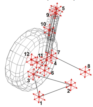
Here you have shown some elements (red & green), which can be seen as the "links" of a suspension. At the ends, of these links you have points (the small spheres) where they would connect to either the chassis/structure or on the other side to the part which holds the wheel in place, called knuckle, upright, strut(housing), wheel carrier, axle(sometimes spindle too) etc.
In this example the points are numbered, and possible force vectors are shown.
here the location of some of the "hard points" (coordinates) is shown as coordinates in 3D space (x-y-z w.r.t. a reference point).
You see the "links" which connect the points with each other.
so in a roundabout way, you could say "hardpoints" are the joints/points where a "suspension link" connects to another part/component.
Another expression, you may find is "coordinates" or "pick-up points".
As Brian said, often the location of some of these points is strictly defined in space (as x-y-z coordinates), mainly in racing, and mainly refering to the chassis side, while the shape & lengths of the "links" is free.
At the end of the day, a first order approach to suspension analysis deals with the geometric relationships / kinematics of the movements. How on part change it's position w.r.t another, a combination of translations (linear movements) and rotations (angular movements). Then on a higher level, you may start to consider the structural aspects, how do these components react when loads are applied (static & dynamic). You may will find, that some parts start to deflect under load, and that the position of some of your "hard points" change when load(s) are applied ( structural deflections / compliance) - this is where the "fun" really starts.
But as a starting point, dig out any good book on kinematics/geometry (preferable 3D), it doesn't even need to be related to "vehicle suspensions", a classical 4-bar linkage is maybe a good starting point, to learn some of the basics.
see here, just for a quick example: https://www.youtube.com/watch?v=zuF4_y4SdT8
if you look around google, youtube etc. you will find plenty of stuff, to keep you busy for a while
good luck
RE: Front Suspension - Geometry hardpoints
MZ7DYJ
RE: Front Suspension - Geometry hardpoints
MZ7DYJ
RE: Front Suspension - Geometry hardpoints
The first diagram is a MacPherson strut rear suspension with parallel (or near-parallel) lower lateral links. The spring and strut compress and extend as the suspension moves up and down. The two lower links "steer" the knuckle that holds the wheel bearing. Since the chassis-end and knuckle-end pivots form a (near) parallelogram in top view with the lower lateral links, the knuckle is held parallel regardless of (reasonable) suspension movement so that you don't get unintended "rear wheel steering". The trailing link guides the knuckle fore/aft as it goes up and down. Although it swings in an arc and therefore will pull the knuckle fore/aft a bit as it does so, the parallelogram effect of the two lower links guides the knuckle so that the wheel stays pointed in the right direction. This also means that the trailing link can have soft bushings in it, to help reduce noise transmitted to the bodyshell and then to the occupants, without this having too much ill effect on the handling, because the rear wheel doesn't "steer" as a result of this.
This is an idealized explanation. In the real world, you might actually want to have the rear wheels "steer" a little bit under some conditions. This can be achieved, for example, by having the chassis-end pivots of the lateral links a different distance apart than the knuckle-end pivots so that it is no longer a parallelogram, or by having the front and rear links different lengths. As mentioned, this is where things start getting messy. But real world suspension designs do indeed account for these effects.
Production vehicles that I know of which use this type of rear suspension design include some generations of Subaru Impreza, Mazda GLC/323/Protege/3, Ford Mondeo/Contour (1980s), Ford Taurus (1980s), Chrysler LH-series (1990s), and I'm sure there are quite a few others.
The second diagram is a very typical MacPherson front suspension, although it could be used as a rear suspension as well. The link between points 7 and 8 define the steering tie-rod. The triangle is the lower control arm. Production examples are too numerous to mention. The majority of modern mass-production cars have front suspension something like this. It can be used as a rear suspension simply by anchoring the steering tie-rod to a fixed location instead of connecting it to the steering rack.
The third diagram is a race-car upper-and-lower-A-arm suspension. The tipoff that it is a race-car suspension is the pull-rod from the vicinity of the upper ball joint that in turn actuates a lever which then operates the spring/damper unit (which is not shown). Open-wheel race cars are like this in order to get the spring/damper unit out of the airflow around the car. Normal production cars that normal people can afford ... can't afford this, and have no need for it since they don't have open wheels.