Dimmer
Dimmer
(OP)
I have disigned a dimmer circuit using Pic12F629. It works fine but with a little electrical noise the pic is resetting. I have added L1 and L2 inductors (see circuit) and some capacitors across the supply but did not solve it completely.
Any idea how to make Pic completely immune to mains noise?
RE: Dimmer
Dan - Owner
http://www.Hi-TecDesigns.com
RE: Dimmer
After adding inductors and capacitors (10nF, 100nF , 1uF, 10uF all ceramic in parallel near the Pic) I noticed a little improvement but not as much as desired.
RE: Dimmer
People sometime try to kill noise with larger capacitors. Actually, a lot of noise issues can be stopped with a very small capacitor applied to the right spot with SHORT LEADS. Long leads on capacitors can negate their effectiveness.
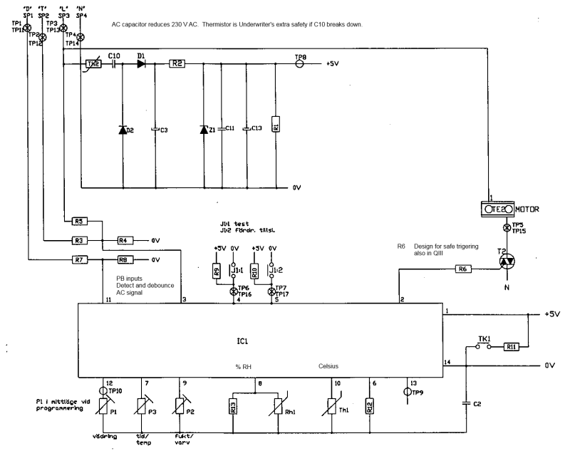
You have I/O ports that are unused - ground them if they're inputs, or at least put a pull-up or pull-down on them even if you're not using them (you might have them active in your code without realizing it, and a long noise burst causing multiple interrupts and quickly put a uP into confusion and into reset. Put a 1nF or 10nF cap on the other inputs. You appear to have plenty of capacitance and filtering on your power supply - enough to power it for a few seconds with power removed. And don't forget the simple tricks - aluminum foil if you suspect a radiated path and not a conducted noise path.
RE: Dimmer
Dan - Owner
http://www.Hi-TecDesigns.com
RE: Dimmer
How much power is being switched by the TRIAC?
If you use a little 7w light bulb as the load, does it still malfunction?
(This is just another possibility for the list...)
RE: Dimmer
I will design another PCB with more shielding and see if it works better.
My last trick would be to save the state in eeprom and read it on reset but that's a little dirty :)
RE: Dimmer
You know antennas? Do the opposite.
Good luck.
RE: Dimmer
Yeah.. That will get you in trouble because you really don't know how many times it's going to happen. You can very quickly burn out the EEPROM. Been there.
Keith Cress
kcress - http://www.flaminsystems.com
RE: Dimmer
Include a screenshot of the scope so we can see what you mean by "noise"...
Dan - Owner
http://www.Hi-TecDesigns.com
RE: Dimmer
I will re-design the pcb and test again and post back - maybe nest week.
Thanks for all the tips suggested.
RE: Dimmer
Dan - Owner
http://www.Hi-TecDesigns.com
RE: Dimmer
Did you investigate if it had any relationship to the current in the load? The 7w light bulb test?
Good luck.
RE: Dimmer
RE: Dimmer
@VE1BLL - I was testing with a small bulb about 25W - dont think a 7W would make much difference.
@MacG - Actually I have another unit ordered and I need to add some things and since the components were through hole I want to change to SMD now. I wish I have more free time but this is partly a hobby for me :)
I am attaching the old PCB design maybe someone can spot any problems. PS - the Inductors and not shown as they were added afterwards.
RE: Dimmer
The one you show has so many issues that I'm surprised it works at all.
There's no ground plane. Your ground meanders around the board from P2-2 to S1-2 like a Monza Circuit. Pour copper for a proper ground plane instead. That is, as I see it, your first and main problem with the design.
There are quite a few more. If this is going to be a commercial product, it will never survive in the market. Too expensive. Too many components. An example of a succesful commercial design is shown below. One of the simplest PICs ever, no A/D. No transformer and still does timing temperature control and humidity control.
We designed that sixteen years ago and the product has now been replaced with a smarter one. So esign is free. It works off a 230 V 50 Hz grid and we had a few problems during beta testing. Adding a ground plane solved those problems.
Gunnar Englund
www.gke.org
--------------------------------------
Half full - Half empty? I don't mind. It's what in it that counts.
RE: Dimmer
Anyway I designed that some time ago and tried to use only 1 layer. I will change to smd now and add proper ground plane.
But I still prefer to use a transformer in my projects instead of the RC circuit.
RE: Dimmer