Continue to Site

Eng-Tips is the largest engineering community on the Internet

Intelligent Work Forums for Engineering Professionals

  • Congratulations KootK on being selected by the Eng-Tips community for having the most helpful posts in the forums last week. Way to Go!

Zero Through-Thickness Bending Stress 1

m_ridzon

Mechanical
Sep 18, 2020
80
Folks, this question relates to ASME stress linearization when being done in ANSYS Mechanical. If I open ASME Sec. VIII, 5-A.4.1.2 and look at Step 2a, it states the bending stresses are only to be included for hoop and normal component stresses.
Screenshot_2024-10-03_165152_tx6ble.png


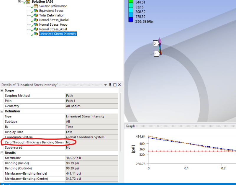
In Mechanical’s post-processing, there is an option to “zero through-thickness bending stress” when linearizing.
Screenshot_2024-10-03_165106_h3qm9h.png


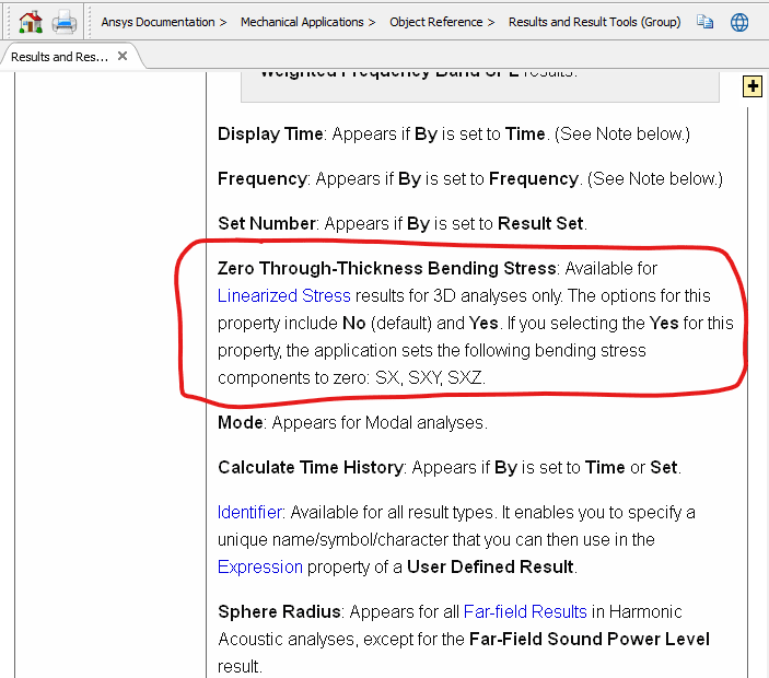
According to Help documentation, if set to Yes, it will exclude SX, SXY, and SXZ bending components (i.e., they will be set to zero). When set to YES, is that option in Mechanical intended to satisfy the ASME requirements?
Screenshot_2024-10-03_164742_eok2kt.png
 
Replies continue below

Recommended for you

@TGS4 thank you!

I have a couple follow-up questions...

[ol 1]
[li]My understanding is that Syz bending also needs to be zero. However, this switch does not zero out that stress component. Would you be able to elaborate on that?[/li]
[li]My cited excerpt is from Sec. VIII. Do you know if this applies to Sec. III as well? If so, is there a spot anywhere in Sec. III that mentions it?[/li]
[/ol]
 
1. I agree that it should be zero, as well. Discuss this with ANSYS.
2. In my opinion, this would also apply to Section III. However, it is not explicitly detailed there. However, the original work that the Section VIII quotation is based on comes from WRC 429, which was written by two Section III engineers. My engineering judgement would lead me to apply it to Section III as well.
 
TGS4 said:
1. I agree that it should be zero, as well. Discuss this with ANSYS.
I will reach out and ask ANSYS. Being that it is what it is, are you aware of a workaround at this moment?

TGS4 said:
2. In my opinion, this would also apply to Section III. However, it is not explicitly detailed there. However, the original work that the Section VIII quotation is based on comes from WRC 429, which was written by two Section III engineers. My engineering judgement would lead me to apply it to Section III as well.
Agreed. That makes complete sense.
 
m_ridzon said:
Being that it is what it is, are you aware of a workaround at this moment?
Manually doing the calculations, based on the software's values of the component membrane and bending stresses (or stress ranges, when the context is for secondary bending stresses).
 
TGS4 said:
Manually doing the calculations, based on the software's values of the component membrane and bending stresses (or stress ranges, when the context is for secondary bending stresses).
Are you saying to manually calculate stress intensity (or von Mises) in a software like Excel, at each point along the cut line, by taking the individual components from ANSYS?
 
The approach is NOT to calculate the equivalent stress "at each point". The approach is to take the membrane (and bending) stresses of each component. Then, using the membrane and the membrane-plus-bending of the appropriate components to form the equivalent stress. It is one calculation, based on the membrane (and the two components of bending) to calculate the equivalent membrane-plus-bending stress.
 
TGS4 said:
The approach is NOT to calculate the equivalent stress "at each point". The approach is to take the membrane (and bending) stresses of each component. Then, using the membrane and the membrane-plus-bending of the appropriate components to form the equivalent stress. It is one calculation, based on the membrane (and the two components of bending) to calculate the equivalent membrane-plus-bending stress.
Yes thank you. I understood that to be the case. However, I don't think I worded my statements the best...I need linearized stress intensity to do Sec. III code qualifications. My understanding is that I have to linearize the 6 components in ANSYS. Then, using the membrane and membrane-plus-bending of the appropriate linearized components, I need to calculate the equivalent stress intensity in Excel for each location along the stress cut line. Is that correct or am I misunderstanding something? I have shown an Excel example below for membrane-plus-bending at three points along a cut line.
Screenshot_2024-10-07_165852_pnrjis.png
 
That looks good to me. Nicely done!
 

Part and Inventory Search

Sponsor