Hello,
Long-time lurker, first-time poster.
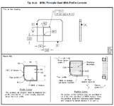
I have a couple of questions pertaining to paragraph 8.8 "Combined Controls" (pp 175-176) in the Tolerances of Profile section in the ASME Y14.5-2009 standard. It mostly has to do with the first example to illustrate the combination of a surface profile callout with a position callout "to control the boundary of a noncylindrical feature". Fig. 8-24 (p176) describes the situation and interpretation:

While I understand the calculations for the tolerance zone and the intent; I have still some doubts about the "validity" of such pair of controls.
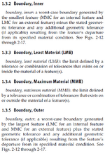
1-First of all, why is the outer boundary of the internal irregular feature of size dubbed LMC; while its inner boundary is called MMB? I have always used MMB, LMB and RMB when talking about datums but I understand why that can be used on any feature.. Are LMC and MMC terms interchangeable with LMB and MMB? If that is the case, I do not understand what the distinction is in section 1.3 p2.

2- If the end goal of the positional control on the surface is to ensure no element of the surface feature lays within an inner boundary contour .6 +.25 = .85mm off the true profile towards the inside, when the cutout is at its MMC ("smallest"); cannot the same goal be attained by using a set of two separate segments FCFs: first with a surface profile callout of 1.2mm; and second with a surface profile control of .85 U .85 back to ABC?
Is this even "grammatically" correct from a GD&T POV; to have a first surface profile segment with no datum called out with a greater tolerance value than the second surface profile segment with datums called out?
3- Is the combination of the profile control and the position control just a subterfuge to achieve the same results as calling out the position of a regular feature of size at MMC, since calling out a surface profile at MMC (or LMC) is not legal? In this case, if the cutout was of a cylindrical shape for instance, that would directly translates to a positional control of .25mm with a (mating) diameter tolerance of +/- .6mm?
4- If 3- is true, then the illustration on the bottom RH corner of figure 8.24 should depict the virtual condition boundary of the irregular feature of size. What about the resultant condition boundary? Is it defined? Would it be correct to assume that no element of the surface feature shall lay outside the outer boundary contour .85mm off the true profile towards the outside? It does not seem to be covered anywhere in the 2009 revision.
5- Then, if 4- is true, wouldn't the same control be achieved by a pair of single segment FCFs (or composite, would not matter) with the upper segment being a surface profile control of 1.7mm back to ABC, and a lower segment of a surface profile w/o datum of 1.2mm? In my opinion, it would make interpreting this specific requirement quite easier.
6-In 2018, I am wondering if there is any way to leverage the dynamic profile modifier?
Thanks a lot!
Long-time lurker, first-time poster.
I have a couple of questions pertaining to paragraph 8.8 "Combined Controls" (pp 175-176) in the Tolerances of Profile section in the ASME Y14.5-2009 standard. It mostly has to do with the first example to illustrate the combination of a surface profile callout with a position callout "to control the boundary of a noncylindrical feature". Fig. 8-24 (p176) describes the situation and interpretation:

While I understand the calculations for the tolerance zone and the intent; I have still some doubts about the "validity" of such pair of controls.
1-First of all, why is the outer boundary of the internal irregular feature of size dubbed LMC; while its inner boundary is called MMB? I have always used MMB, LMB and RMB when talking about datums but I understand why that can be used on any feature.. Are LMC and MMC terms interchangeable with LMB and MMB? If that is the case, I do not understand what the distinction is in section 1.3 p2.

2- If the end goal of the positional control on the surface is to ensure no element of the surface feature lays within an inner boundary contour .6 +.25 = .85mm off the true profile towards the inside, when the cutout is at its MMC ("smallest"); cannot the same goal be attained by using a set of two separate segments FCFs: first with a surface profile callout of 1.2mm; and second with a surface profile control of .85 U .85 back to ABC?
Is this even "grammatically" correct from a GD&T POV; to have a first surface profile segment with no datum called out with a greater tolerance value than the second surface profile segment with datums called out?
3- Is the combination of the profile control and the position control just a subterfuge to achieve the same results as calling out the position of a regular feature of size at MMC, since calling out a surface profile at MMC (or LMC) is not legal? In this case, if the cutout was of a cylindrical shape for instance, that would directly translates to a positional control of .25mm with a (mating) diameter tolerance of +/- .6mm?
4- If 3- is true, then the illustration on the bottom RH corner of figure 8.24 should depict the virtual condition boundary of the irregular feature of size. What about the resultant condition boundary? Is it defined? Would it be correct to assume that no element of the surface feature shall lay outside the outer boundary contour .85mm off the true profile towards the outside? It does not seem to be covered anywhere in the 2009 revision.
5- Then, if 4- is true, wouldn't the same control be achieved by a pair of single segment FCFs (or composite, would not matter) with the upper segment being a surface profile control of 1.7mm back to ABC, and a lower segment of a surface profile w/o datum of 1.2mm? In my opinion, it would make interpreting this specific requirement quite easier.
6-In 2018, I am wondering if there is any way to leverage the dynamic profile modifier?
Thanks a lot!

