retired13
17 Jun 20 00:04
That is correct, if the point load at B is 500, not the 550 you have shown, and there is a pinned support at A. Unfortunately, we were talking about a roller support at A. And, yes the arrow on the joint from BD's axial tension load should be reversed showing direction to the right. Unfortunately that change in direction unbalances the summation of
horizontal forces at B.
-870 /12.65 * 4 = -825
2451 /12.65 * 4 = +2325
1500 to right = +1500
[highlight #FCE94F]Sum Fh at B = +3000 that isn't 0
[/highlight]
BAretired
17 Jun 20 01:20
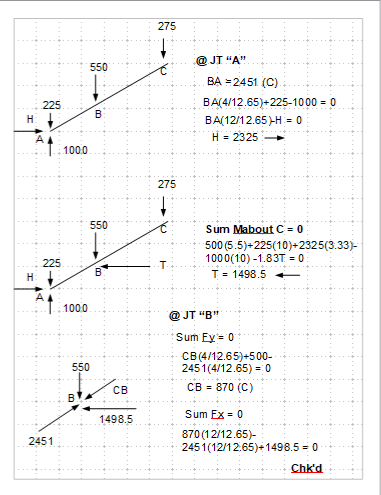
Sand bag at C is 275. We need only analyze 1/2 the structure, to the left of its centerline, therefore 275. The other half of the structure to the right of centerline takes the other 275, but we are not concerned about that half. There is no need to consider your additionall 275 load.
I am not sure why you have the 550(20)/4 in your line showing M = 500(4.5) + 550(20)/4 = 5000'#
The load is not 550 and the distance is not 20/4, so what is this?
Now, your lines,
M@B = 775*4.5 = 3487.5 (from forces at A)
M@B = 500*4.5*5.5/10 + 2727*1.5*1.8333/3.3333 = 3487.2 (Beam ABC moment)
M@B = 2727*1.8333 - (550/2)5.5 = 3487 (from forces at C)
The first line is OK, the internal moment at B is 3487.
But I don't understand what the second line is doing. Something about Pab/(L/2) and the tie force x h1 x h2 / h? Would you please explain what that is?
The third line appears to be balancing moments at C at the start, because 1.8333 * 2727 is the distance from C to tie and 2727 is the tie force, however you have written B). The distance from B to tie load is 0.
And finally the 550/2 (=275) point load placed 5.5 away from B could only be putting that load at C, indicating you are balancing B. So are you balancing moments at B or C? And I note that the net reaction at A of 775 up is not included at all, except in the first line.
I don't know why it takes 3 lines of different equations to balance moments at any point. One equation showing a sum of moments =0 will do. Then we can work on summing the Fv and Fh equations.
BAretired
17 Jun 20 04:20
" With pin/roller, the structure is determinate, so member stiffness does not come into play."
To ensure that the structure does not fall down, member stiffnesses of ABC and CDE must be relatively large. That's definitely in play.
Retired13
17 Jun 20 05:29
[highlight #FCE94F]Now we are getting somewhere. This is important.[/highlight]
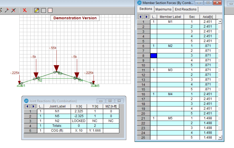
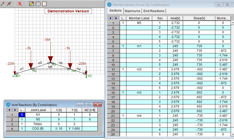
M5 axial load is 2732. Good! Agrees closely with a sum moment at C solution.
M1 axial load is 245, not zero as a roller support might indicate in a determinate structure analysis, however the shear load in this member and moment at B must be doing the bulk of the work in resisting the 775 net load there at A without needing to generate a large axial load. Shear in M1 is 735, which is close enough for me to say that it is shear and bending moment are indeed resisting the net reaction load of 775. So not much axial force is needed to do so. So if we attempt to balance forces at B, we must not only consider axial loads, as in a truss. We must also consider the shear loads being dumped into that joint from members m1 and m2. [highlight #FCE94F]Shear loads dumping into joint C must also be considered when balancing Fh and Fv at joints of indeterminate structures we must consider Vh and Vv,[/highlight] not just the axial loads.
I have deleted the Dropbox file until such time that I can add shear loads into the joint balances.
Thank you both for the grey matter exercise. I am vary happy with the outcome. I'm good. Now I can analyze the indeterminate structure by assuming that any unbalanced axial forces must be resisted by adding the appropriate amount of shear into the respective members.
“What I told you was true ... from a certain point of view.” - Obi-Wan Kenobi, "Return of the Jedi"