Continue to Site

Eng-Tips is the largest engineering community on the Internet

Intelligent Work Forums for Engineering Professionals

  • Congratulations waross on being selected by the Eng-Tips community for having the most helpful posts in the forums last week. Way to Go!

Wood Diaphragm to Wood Shearwall Anchorage 1

Status
Not open for further replies.

Jerehmy

Structural
Aug 23, 2013
415
Searched around, couldn't find anything that addresses my specific question.

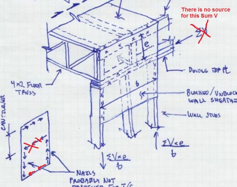
For those that have Breyer 6th edition, Figure15.3b shows the connection situation I have a question about.

The diagram shows a framing anchor to connect the double wall top plate (chord) to the rim joist. It also says other connections such as toenails or blocking could be used in lieu of the framing anchor.

Why not just use the wall sheathing? I am racking my brain and can't figure out a reason why. Looked all over online and couldn't find anything. I feel like I'm overlooking something.
 
Replies continue below

Recommended for you

Id say the compression wouldn't be much different. We'd have that 2x stud at the end.
 
Another wrinkle with the floor truss example is that you're unlikely to get the trusses, studs, and sheathing joints to line up. That doesn't invalidate the load path but it definitely makes it messier.

I like to debate structural engineering theory -- a lot. If I challenge you on something, know that I'm doing so because I respect your opinion enough to either change it or adopt it.
 
What if we just fastened those 2x's to the top plate, for arguments sake. I'm just curious what the tension would be.

2kip wind shear, ASD. so 4kip*ft. Let's say its continuous and 30ft long. So 4/30 = 133#. A single screw could do that and we'd be able to maintain the shearwall.

Yeah seems the loads are nothing to worry about. Even for much larger buildings, I can't see them getting too big.

I feel better about the situation now. I was worried I was overlooking something major.
 
At 133#, you could probably make due with just resisting dead load.

I like to debate structural engineering theory -- a lot. If I challenge you on something, know that I'm doing so because I respect your opinion enough to either change it or adopt it.
 
I was about to post the combined uplift and shear detail. I think that is an OK detail, no? Kootk, you're not a believer?

As for the cantilever - you have the end of the joists supporting the rim boards which would counteract any downward/upward force from the cantilever. So its really like a cantilever with a moment resisting support at the top. Free to translate but not rotate. I suppose there is still some flexural force though.


EIT
 
Sorry KootK - I don't buy your iso drawing. You show a SumV value where there is none.

The double top plate has no way to create a Sum V force as it is simply a loose double top plate attached to the sheathing itself.

I could draw a free body diagram of the full height sheathing (bottom of wall to top of rim board) and have a complete static condition without the "cantilever" action you are attempting to show. Simply sheathing in pure shear from top to bottom.

Again - for there to be a cantilever with a cantilever span of "e" per your diagram
Iso_j2c38b.jpg
the double top plate must have something (finger of God) holding it from moving laterally and there isn't anything but the sheathing. But the sheathing cannot cause its own moment.


Check out Eng-Tips Forum's Policies here:
faq731-376
 
For this construction, the rim joist is actually a rim truss - similar to an end wall truss.

The double top plate is a shear collector, from the roof or floor diaphragm to the shear elements below, particularly if it is needed to limit the h/d ratio to 3.5 or less, as in perforated shear walls.

Mike McCann, PE, SE (WA)


They're 2x on the flat. That'd only leave 2" bearing on the 2x6 double top plate. That'll work for calcs but 4" bearing with cantilevered sheathing sounds better to me. Would you only have 2" bearing?

They have cabinet file storage in this attic so the truss have double top and bottom chords. pretty decent reactions but 2" would probably work for Fcp.
 
RFreund said:
I was about to post the combined uplift and shear detail. I think that is an OK detail, no? Kootk, you're not a believer?

I was a little skeptical. I gave it a good read last night, however, and I'm on board. KootK approved!

Rfreund said:
As for the cantilever - you have the end of the joists supporting the rim boards which would counteract any downward/upward force from the cantilever. So its really like a cantilever with a moment resisting support at the top. Free to translate but not rotate. I suppose there is still some flexural force though.

Agreed. This bears some similarity to the strut and tie mechanism that I mentioned above. I would think that it would be less true for a floor truss ribbon and approach more true for something like full depth rim board.

JAE said:
Sorry KootK - I don't buy your iso drawing. You show a SumV value where there is none.

Jeez... I was wearing braces the last time that I got three red exes on a single page assignment. My kids loved this and request more of the same.

I muddied the waters in my original sketch when I indicated that the collector force in the top plate would be SUM(v). In general, it will not be SUM(v). Rather, the collector force could take on just about any value, positive or negative, depending on the relative stiffness of the various vertical bracing elements up and down the line. See sketches A, B, and C below for an example of a case that would yield a shear flow diagram consistent with my original sketch.

The "finger of god" force is really a red herring when it comes to this debate however. The statics of the cantilevered sheathing above the top plate remain the same regardless of the value of the top plate collector force. See sketches D, E, and F below for the statics when there is no divinity at play. Panel two just cantilevers from panel one, without the benefit of discrete chords.

Capture_A_fxloxt.png


Capture_B_rojwin.png


I like to debate structural engineering theory -- a lot. If I challenge you on something, know that I'm doing so because I respect your opinion enough to either change it or adopt it.
 
So the whole shear wall is a cantilever off the footing.
I'm not sure why then there is any concern over a small portion of that "cantilever" up at the top.

Your earlier statement "a minor technical hiccup to consider" concerning this cantilever isn't a hiccup at all - simply a feature of any typical shear wall, correct?


Check out Eng-Tips Forum's Policies here:
faq731-376
 
Perhaps wood sheawalls, but not CMU where reverse curvature can occur.

Mike McCann, PE, SE (WA)


JAE said:
I'm not sure why then there is any concern over a small portion of that "cantilever" up at the top.

There is no real concern on my part. I tabled this as an explanation for why we don't see details like Jerehmy has proposed in the literature.

JAE said:
Your earlier statement "a minor technical hiccup to consider" concerning this cantilever isn't a hiccup at all - simply a feature of any typical shear wall, correct?

Not in my opinion. The unique feature here, in my mind, is that the upper portion of the shear wall doesn't have vertical "chords". That means that flexure has to, briefly, be resisted by bending stress in the sheathing. The design methodology that we generally use for wood diaphragms assumes that sheathing is only loaded in shear. This issue doesn't develop with typical detailing where blocking or rim board acts as a mini-diaphragm to transfer shear from the roof diaphragm to the shear wall top plates.

I don't feel ambitious enough to dig up the clause references but both the US and Canadian wood design codes contain language to the tune of "all wood diaphragms shall have discrete boundary elements on all sides". This is an expression of the "shear only panel" assumption built into our standard wood diaphragm design methods. Technically, Jerehmy's detail could be construed to be in violation of these clauses. I'm not, for a second, suggesting that anybody over at the AHJ is going to flag this however.

I like to debate structural engineering theory -- a lot. If I challenge you on something, know that I'm doing so because I respect your opinion enough to either change it or adopt it.
 
With all the adjoining joists/trusses, etc. the panels are typically nailed all around. I can see the issue at the edges where in tension there might be some discontinuity in the panel. Typically there are inter-story straps if this is a floor so the panel would be completely covered with perimeter elements on all sides. For roofs, maybe not. On the compression side there isn't much, if any, difference.

But overall this appears to me to be a minor issue. I was just responding such that I agree with manstrom way above.
The sheathing can be extended (assuming panel sizes work and no joints in the panels) and simply transfer the shear to answer the original poster's question.

Check out Eng-Tips Forum's Policies here:
faq731-376
 
Status
Not open for further replies.

Part and Inventory Search

Sponsor