Continue to Site

Eng-Tips is the largest engineering community on the Internet

Intelligent Work Forums for Engineering Professionals

  • Congratulations cowski on being selected by the Eng-Tips community for having the most helpful posts in the forums last week. Way to Go!

Which CAD was used to design Stratolaunch?

Status
Not open for further replies.

PrintScaffold

Mechanical
Sep 8, 2006
453
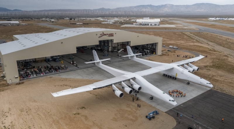
Very impressive! Does anybody know which CAD did they use? Was it NX, CATIA, or something else?

stratolaunch-rollout_kykesx.jpg


Replies continue below

Recommended for you

I wonder why they have (apparently) two flight decks ? There have been several airplanes with twin fuselages, but typically only one flight deck.

another day in paradise, or is paradise one day closer ?
 
The flight deck on the left is empty and unpressurized. Future options I guess. (There's a link on Drudge today for the whole story.) I'm not in aerospace but it is my understanding that Catia is the preferred tool for aerospace design.
 
Looks like the pilot and copilot have had a spat.
 
Job postings note a preference for Solidworks (or equivalent) in CAD experience. The first handful of employees that've worked on it, which I found on LinkedIn, claim proficiency in many CAD/CAE software packages, though.

Otherwise can't really tell. Solidworks is apparently being used by more larger scale projects like this. A friend of mine who worked at Firefly before a recent downsizing said that's what they used. I was quite surprised, expecting something more like you mention - NX/CATIA or maybe Pro/E or something with similarly advanced analysis functions. Using Solidworks and external CAE analysis and simulation software like Ansys is apparently not uncommon in advanced engineering companies like these, though.
 
But we do know that the engines were designed using NX.

John R. Baker, P.E. (ret)
EX-Product 'Evangelist'
Irvine, CA
Siemens PLM:
UG/NX Museum:

The secret of life is not finding someone to live with
It's finding someone you can't live without
 
The lack of elegance of curvature on the fuselage indicates SolidWorks.
 
TheTick said:
The lack of elegance of curvature on the fuselage indicates SolidWorks.

Honest question: What is lacking in SolidWorks that is needed to generate more complex curves? Do higher-end CAD systems have dedicated tools for this type of task?

I cannot imagine a shape that I couldn't make in either of the lower-end CAD systems that I have experience in, SolidEdge and SolidWorks. However, I fully admit that my imagination may be the limiting factor here; aerodynamic, flowing shapes have never really been my job.
 
It's got this weird look of some sort of advanced-beginner training model. Not speaking so much to the capabilities of SW so much as the type of design that often emanates from middle-of-the-road users venturing into more daring territory for the first time.

Fuselage looks like a pair of scaled-up Cessna 172s with B-1 noses scabbed on. "Corners" of rear half of fuselage are not C2 continuous. Flat side walls surrender a lot of structural integrity inherent with a more cylindrical/conical shape.

I can only speak about CATIA from the perspective of a downstream client. However, I had a lot of "under the hood" experience with UG/NX surfacing. If I was designing ANYTHING with math-critical surfaces, it would be in NX or CATIA (not even Creo).
 
I did some work on the MLG integration at a subcontractor and everything we did was in CATIA V5.
 
The space between the fuselages is for payload and I had assumed the flat sides were deliberate to maximise that space. . . . Or perhaps they were designed in Solidworks.

je suis charlie
 
If they truly -did- do the structure in SW it would be the first I'm aware of. The only people I know, personally, who use SW in an aerospace context have used it for engines and mechanical systems.

Solidworks and other "middle of the road" CAD packages have come a long way since I last worked with them several years back. They have been incorporating a lot more freeform surfacing tools, flow and thermal analysis, and some FEA tools. I have not used any such tools. I was just surprised to learn of it. It's possibly just something that makes 'pretty pictures' that will make minor/less-critical design work "look better" or make pretty pictures for advertising materials that make them look like a more advanced/competent engineering team... or maybe it's pretty legit. I dunno. The people I know using Solidworks use more established CAE tools.
 
I find it hard to believe that the shape is limited by the capabilities of the CAD tool. Sure SW is seen as CATIA-lite. I suspect that the licence fee is lower and the capabilities similar. Someone starting out now has more options that 10 or 20 years ago, and isn't married to the big CAEs (CATIA, PATRAN, NASTRAN).

I think the shape is the shape they want, from CFD. Flat sides improve the wing end plate effect, I doubt the the payload has much impact on this design decision. Those enormous MLG bogies must be murder to retract (into a sensible shape).

As for the second cockpit ... maybe that's reserved for payload operating crew ?

another day in paradise, or is paradise one day closer ?
 
The round shape of most higher altitude transport aircraft come from the fact that they are basically flying pressure vessels built for human "cargo". The payload for this aircraft is all external (between the fuselages). I would bet that the sections with flat walls are not pressurized (thus not intended for humans), so their construction could be simple rectangles. I would guess that the only areas intended for possible human occupancy are the cylindrical shaped front sections of the fuselages. The article I read said that the crew is in the right flight deck. The left one is vacant and unpressurized. The left one was probably designed that way for aerodynamic symmetry and for potential later occupancy.

Interestingly, just this morning I saw a picture in the book "How to Make a Spaceship" of Burt Rutan (designer of the above aircraft) when he was 10 years old with one of his first homebuilt balsa wood and paper model airplanes. I can highly recommend that book for anyone interested in the development of commercial spacecraft.
 
It looks like since it's a one off or small fleet plane, that the design and tooling figure large in the project cost. I think this is a case of making one thing twice is easier than making two similar things once.

SCI can certainly make beautiful and crazy things without a straight line in them, however they get to lines on paper and coding in machines. The 'liquid shape' aspects of the thing may not have been critical, that the approach of sistering a couple giant Short 360's solved their problem. I think the FBW aspects of the thing must be very interesting. With the weak but significant fuselage coupling, it must be like operating a couple large planes in formation, except if you break formation, everyone dies.
 
From:
"To cut development costs, many of the aircraft systems have been adopted from the Boeing 747-400, including the engines, avionics, flight deck, landing gear and other systems. Two former United Airlines Boeing 747-400 aircraft (Serial numbers 28715 & 28716) were acquired and taken to the Mojave Air & Space Port for cannibalization."
 
The White Knights 1 & 2 do something similar, two identical looking fuselages instead of a right and left hand.
 
Status
Not open for further replies.

Part and Inventory Search

Sponsor