Continue to Site

Eng-Tips is the largest engineering community on the Internet

Intelligent Work Forums for Engineering Professionals

  • Congratulations cowski on being selected by the Eng-Tips community for having the most helpful posts in the forums last week. Way to Go!

Where to use Redundancy Factor=1.3? 3

Status
Not open for further replies.

Osama Anwar

Civil/Environmental
Jun 28, 2020
14
If I have a Symmetrical Special moment resisting frame in SDC D with 3 bays in one direction and 8 bays in another direction and I am solving it in ETABs and have enabled P-Delta effects, will I use redundancy factor=1 or =1.3. Is there any way to access redundancy factor without calculation if not then how the calculation is made?
 
Replies continue below

Recommended for you

Reundancy factor is a penalty factor applied to less redundant structures for SDC D thru F and for extreme torsional irregularities for SDC D. Notice that extreme torsional irregularities are not allowed for SDC E and F .


Look to ASCE 7 section 12.3.4 which describes the methodology for determination of the redundancy factor, ρ .

There are two values of the redundancy factor: 1.0 and 1.3 . Pls look to Table 12.3-3 ( Requirements for Each Story Resisting More than 35% of the Base Shear) for t he calculation requirements..If the failure of a single element of the seismic force-resisting system will result 33% reduction in story strength, or does the resulting system have an extreme torsional irregularity, penalty factor of 1.3 is used.

There are two tests ; aspect and calculation ..If you post the structural plan, you will get comments for aspect , regarding calculation, you shall carry out the calculations mentioned Table 12.3-3 .
 
Annotation_2020-06-27_161419_udvzxw.png


I have no extreme torsional irregularities so can I use ρ=1?
 

Aparently , the picture depicts , thre is no plan irregularities..However , visiually fails the configuration test described in subparagraph (b) of 12.3.4.2 Redundancy Factor, ρ, for Seismic Design Categories D through F.

I have copied and pasted that para.: (Structures are regular in plan at all levels provided that the seismic force-resisting systems consist of at least two bays of seismic force-resisting perimeter framing on each side of the structure in each orthogonal direction at each story resisting more than 35% of the base shear.......)

You are expected to provide two V.B. (for steel SMRF ) or SW ( for R.C. SMRF) at short direction , far ends...

If you hesitate to add SW or VB, you are expected to use penalty clause ρ=1.3.

I feel, one of the firs three modes is torsional mode and this is not acceptable.
 
Is requirement of ρ only applicable for RSA or it is also needed in ELF method
 
Get the code out and read it. For something so important, it’s best to read and understand the provisions for yourself rather than ask strangers on the internet. There are just a few sections which address redundancy - it’s pretty straightforward.

 
For ρ to be 1, code says "Each story resisting more than 35% of the base shear in the direction of interest shall comply with Table 12.3-3." and for Moment resisting frames it is stated in Table 12.3-3 ,"Loss of moment resistance at the beam-to-column connections at both ends of a single beam would not result in more than a 33% reduction in story strength; nor does the resulting system have an extreme torsional irregularity". How do I check "Loss of moment resistance at the beam-to-column connections at both ends of a single beam would not result in more than a 33% reduction in story strength"?
 
And yeah I am hesitant to add SW. I know my plan do not satisfy subparagraph (b) of 12.3.4.2 but I wanted to know is there any chance it would be satisfying subparagraph (a) of 12.3.4.2?
 
1) All of the beams shown in blue in your sketch are, in fact, moment frame beams correct? Unless I'm missing something important here, this building strikes me as a no brainer for ρ=1.0.

Osama said:
I know my plan do not satisfy subparagraph (b) of 12.3.4.2

2) Why not? Based on what you've shown us, I would think that clause would be satisfied.

Osama said:
but I wanted to know is there any chance it would be satisfying subparagraph (a) of 12.3.4.2?

3) I agree that clause would be satisfied unless there's something weird going on vertically that you've not shown us.

Osama said:
How do I check "Loss of moment resistance at the beam-to-column connections at both ends of a single beam would not result in more than a 33% reduction in story strength"?

4) My interpretation would be this for a single level of a single framing line:

a) count the total number of beam-column joints that are part of moment frames on the line in question, at the level in question, and make that [n].

b) IF [2/n < 0.33] THEN all good.

It's not necessary here from what I can see but I could easily justify an even more liberal interpretation for the short building direction based on, I assume, your having a grid network of moment frames on this project.

C01_wskdco.jpg

c02_tbojnw.jpg
 
Thanks for the reply.
1) Yes blue lines are beam.
2) Yeah, you are right. My understanding of the clause was flawed. You are right. It would satisfy.
3) No, vertically it is same.
4) So if I have a 4 story building with 3 bays in short direction then my n would be 4*4=16, right? or 4. If I am wrong then please elaborate 'n'?
I guess I would be using ρ=1 then.
Once again thank you for such a comprehensive reply.
 
In a highly redundant perimeter moment frame, (imagine a 10 bay MRF), removal of a single beam would not cause a high reduction in strength nor will it produce an extreme torsion irregularity. However, removal of beam in a one or two bay moment frame may cause a reduction in strength more than 33 percent, which in turn may or may not cause an extreme torsional irregularity. Accurate redundancy calculations would only be required for such systems.

If you don’t have enough experience to make such decision by only inspection of a structural system, you can easily determine the effect of “loss of beam-column moment connection” on a story by releasing the end moment of a particular beam and compare the DCR of critical frame members from both models. If the DCR of latral load resisting members is increased by 33 percent then you need to consider the redundancy factor of 1.3.

(Edit) Alternatively:
You can also find the lateral stiffness of each story for both models. If the lateral stiffness of modified model is reduced by 33% then you need to consider the redundancy factor of 1.3.
 
Osama Anwar (Civil/Environmental)(OP) said:
For ρ to be 1, code says "Each story resisting more than 35% of the base shear in the direction of interest shall comply with Table 12.3-3." and for Moment resisting frames it is stated in Table 12.3-3 ,"Loss of moment resistance at the beam-to-column connections at both ends of a single beam would not result in more than a 33% reduction in story strength; nor does the resulting system have an extreme torsional irregularity". How do I check "Loss of moment resistance at the beam-to-column connections at both ends of a single beam would not result in more than a 33% reduction in story strength"?

Mr. ANWAR, I do not look to threads everyday... Regarding ' Loss of moment resistance at the beam-to-column connections at both ends of a single beam would not result in more than a 33% reduction in story strength'..the configuration of the columns implies , the widths of the frame elements restricted with wall thk.

One can say without calculation, removing one of the beams will not cause to a reduction by more than 33% of the lateral strength of the structure. However, can not say without calculation , the removing of a beam will not cause excessive torsional irregularity.

You are expected to perform calculation to test for torsional irregularity. Calculate the maximum story drift with removing one of the side beams at far end , including accidental torsion (with eccentricity of 5% of the width ) and compare the story drift at one end of the structure with the average of the story drift.

If more than 1.4 times , you have two options ; either use ρ=1.3 or reduce the torsional irregularity by using ( more stiff columns and beams or adding SW at far ends.).

I proposed to add SW to far ends at short direction, with feeling the torsional mode would be primary mode which is not wanted.

Good luck.


Mr. HTURKAK, How my plan does not satisfy subparagraph (b) of 12.3.4.2 isn't special moment resisting frame (SMRF) a type of seismic force resisting system? I have 4 frames in one direction and 9 in other.
By far end you mean far end in shorter direction, right? or longer direction. And of upper most story or lower story?
 

Mr ANWAR, Redundancy Factor, ρ, shall be checked for each story resisting more than 35% of the base shear. In ur case if the no. of stories 10, the uppermost 3 stories could be be exempt from redundancy check.

The plan you provided is rectangular and aspect ratio W/L around 2/5. That is, prone to torsional weakness.

Consider short direction, remove one of the beams at Y axis , say Y/ 2-3 , and add accidental torsion 5 % of L , and check for extreme torsional irregularity. With visual inspection, assume story shear V= 90 units ,each frame in short direction will resist to 10 units. If you , remove the mentioned beam, the resistance of that frame will reduce around to 6 units. Total ecc. will be (0.05 W+ (4*4/90)*W ) around 0.23 W.

Calculate the maximum story drift, including accidental torsion and with removed beam . Check the drifts and compare with the average of the story drifts. If the drift at one end of the structure is more than 1.4 times of the average , the structure has extreme torsional irregularity. Pls look Table 12.3-1 Horizontal Structural Irregularities 1b.
 
If your S1 is greater than 0.75, then you are in SDC E and rho is 1.30 regardless.
 
My building is 4 story (G+3) + a pitched roof above. But only 4 stories resist more than 35% of base shear. So I exempted roof from the check.
I did the following process.
1) Removed the beam from Y/2-3 in 4th story. (Do I need to check for other stories?).
I noticed story shear reduction of less than 1 kips (original was 177 kips)
2) Then I checked for mode 3 as follows
 
 https://files.engineering.com/getfile.aspx?folder=fe1de2a1-1877-4e85-905a-7550315e80cb&file=Screenshot_(68).png
Osama said:
Once again thank you for such a comprehensive reply.

You're most welcome Osama, it's an important question.

Osama said:
So if I have a 4 story building with 3 bays in short direction then my n would be 4*4=16, right? or 4. If I am wrong then please elaborate 'n'?

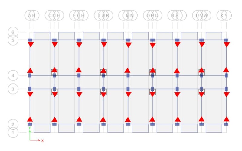
You'd do the calculation floor by floor. With reference to the sketch below:

1) I wouldn't count the beams over the corridor as moment frame beams but that is probably a discussion for another thread. Still, I'll leave those out here.

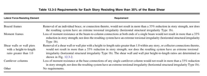
2) I count 18 moment frame beams and 26 moment frame beam to column joints in the plan below. So n = 36

3) 2/n = 2/36 = 5% which is much, much, much less that 33%.

4) With your very well distributed, and highly symmetric lateral system here there's zero chance that the removal of any one beam will result in a torsional irregularity much less an extreme torsional irregularity.

It's important to recognize that the particular lateral system that you're using here is:

1) Extraordinarily redundant and;

2) About as torsionally regular as they come.

The redundancy penalty is really meant for the kind of modern building that gets built in North America and elsewhere where your lateral system consists of just a few isolated elements, something like:

a) An external stair shaft at one end.

b) A steel K-brace straddling some windows at the other end.

c) A chimney stuffed full of dead cats somewhere in the middle.

Your building ain't that. Not by a long shot.

If every column in every building were part of a bi-directional moment frame, as is the case with your building, there wouldn't even be such a thing as a redundancy factor. It would be a pointless waste of human effort.

 
Status
Not open for further replies.

Part and Inventory Search

Sponsor