Continue to Site

Eng-Tips is the largest engineering community on the Internet

Intelligent Work Forums for Engineering Professionals

  • Congratulations waross on being selected by the Eng-Tips community for having the most helpful posts in the forums last week. Way to Go!

What is this actually mean of this drawing acc. to CMM operator? Urg. Help Please !

Status
Not open for further replies.

umitki

Automotive
Mar 11, 2018
2
Dear All,

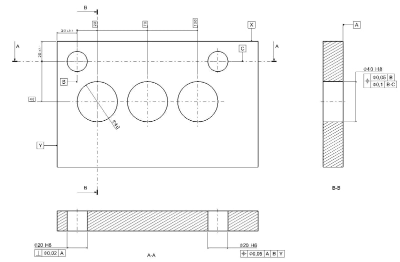
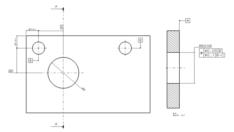
What is this drawing actually mean for an operator. I mean, how will i orientate this part while measuring at CMM.
Also position tolerance of center hole (Ø50) is that right? How can we give a position tolerance information of a hole according to one datum ( Datum B, position tol: Ø0,05 ) ?
I need an urgent help, best regards.!!

Ex-1_x9cvcm.jpg
 
Replies continue below

Recommended for you

What standard are you using/ is shown on the drawing?
If ASME Y14.5 composite callout in the section view is wrong callout.
Might be correct (but not sure if functional) if position shown is changed to multiple single segments (two position callouts).

On CMM I would drive an axis in the middle distance between axes driven from hole B and hole C.
 
The drawing makes no sense. It looks like an uninformed attempt to use implied datums and suggest that only certain directions are to be used from the related features. Ask the supplier of the drawing to explain what they want and provide instructions.
 
umitki,

You show datums[ ]B and[ ]C applied to centre-lines. Datums must be applied to physical features. You can apply them to the holes!

--
JHG
 
Just throwing my hat in the ring here too. This drawing is toast. The responses here totally reflect the responses in the CMMguys forum where you posted this first.

If you attempt to check this part to this print just like it is, you are just generating numbers that don't mean anything.

John Acosta, GDTP Senior Level
Manufacturing Engineering Tech
 
Here are some observations:

1. Like pointed out by drawoh, B and C datum feature symbols should be connected by leaders to the circular outlines of the holes. Not to any centerlines.

2. Question about the composite control on dia. 40: is the first segment referncing only B meant as an orientation refinement of locational position with reference to B-C? If so, switch places between segments. Also, it's a bit unusual to see position refinement referencing a nominally parallel datum. Usually it is meant as a perpendicularity refinement. I wonder what the others will have to say about that.
Another thing - you need a basic dimension from that hole to the plane through B and C. (My bad, you already have the 40 basic dimension).

3. You need to loacte the upper right small hole to datum feature hole B, with basic dimension.

4. The directly toleranced location coordinates of datum feature hole B should be basic and it should have a position call out to A, X and Y datums. Locating a feature of size by +- tolerance is not considered a recommended practice.

The others will probably point out additional issues.

semiond
 
Status
Not open for further replies.

Part and Inventory Search

Sponsor