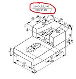
That note (label) describes 2 holes on the top of the part; the "M6" means the holes are threaded with a Metric size of Ø6mm. the "DEEP 20" means the threaded portion of the hole is 20mm long (so the 2 holes do not go all the way through the part)
CATIA has a command called the Hole Wizard which will add the holes parametrically to the model. (Click on the Hole Wizard icon and hit F1 for Help, or google search for videos on how to use it)
When you do add threaded holes to a CATIA part, CATIA does not show the actual threads. (this is done to conserve graphics processing, as threads can be very graphic intense) The threaded holes will look just like drilled holes. But when a multi-view drawing is made from the part, the threaded holes will be shown with the standard thread symbols.