Continue to Site

Eng-Tips is the largest engineering community on the Internet

Intelligent Work Forums for Engineering Professionals

  • Congratulations 3DDave on being selected by the Eng-Tips community for having the most helpful posts in the forums last week. Way to Go!

What is the boundary conditions for beams welded on a steel plate, and Spring constant values

Status
Not open for further replies.

Ndrds20

Structural
Nov 6, 2020
4
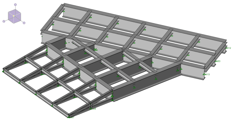
Rendering_of_Structure_wpt3vl.png
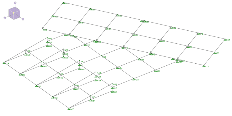
Wireframe_of_Structure_q4qe0l.png
I’ve got questions about boundary conditions for my beams, and values of spring constants, and hope that someone familiar with these topics can advise. First question is I have a structure consisting of beams, some as deep as 24”, and even a small triangular truss. It is a very low structure. The highest point is only the depth of the 24” beam. There are tied together with other members and cross members to form a rectangular frame. There is a small triangular truss framing into this rectangular frame. The whole structure is then welded to a ½” thick steel plate and the whole steel plate is set on top of a roadway. The purpose of this frame is to allow pipes to cross the roadway. The roadway cannot be disturbed in any way because of a specific reason. Now, what is the boundary conditions between the beams and the steel plate. Now, the beams are welded, or even bolted, to the steel plate. Would it just be a pinned or fixed condition, depending on how the beam is attached to the steel? Initially, I was thinking about spring constants, too, but after further thinking, I believe that spring constants has nothing to do with the beam. The spring constants will be the supports for the steel plate underneath the whole structure, but that’s for another day.

Second question is about the spring constant. My ½ inch steel plate is seated directly above the roadway. The Geotech has decided that the modulus of subgrade location there is 100 pci. I need to input the spring constant in my software as a k/in. To convert from pci to k/in is just to multiply by the area of the “support”. I saw a calculation done here for a soil that had a modulus of subgrade reaction of 75 pci. The area of the “support” was taken as 1 SF. Thus, 75 pci * 1 SF * 144 Sq In/1 SF result is 10800 lb per inch, or 10.8 k/in. However, what area of support do I use? How often do I space my spring constants? I guess, the area of support would be dependent on how often I space the springs.

Third question. Same situation as the second question, but now, I have a beam seated directly on the ground. Same subgrade modulus as before, say 100 pci. What area of support do I use? Would this be dependent on how far I space my springs?

Sorry if I am not very clear in the description of my conditions. If you have any questions, please ask. Thanks in advance.
 
Replies continue below

Recommended for you

In general, your boundary conditions for a connection are either fixed or pinned depending on how the connection is made (Are the flanges connected or just the web? Does the connector have a mechanism for allowing rotation like twisting of an angle or horizontal movement in the bolt holes?), so we would need to see the exact connection details to give you an answer. If you're attaching it to just a steel plate, though, it may be pinned regardless of how it is connected just because of the flexibility of the plate. The reality is that the connection will be somewhere between fixed and pinned so if there is uncertainty then it is best make sure your structure will work for both conditions.

The area for your spring supports depends on the actual bearing area and how often you model the supports. If your plate is 2 feet wide and 10 feet long, for a 2D model you could create 10 spring supports with a 12" spacing, then each will be supporting a 24" x 12" area so you would have 100pci * 24in * 12in = 28,800 lb/in = 28.8 k/in.

Structural Engineering Software: Structural Engineering Videos:
 
I have attached some screenshots of a rendering and then a wireframe of my structure. It is a really low structure. It is meant more for a pipe crossing and vehicles are able to drive over it, too. I have a 1" steel plate at the top of the structure, and a 1/2" steel plate at the bottom of the structure. I just want to be sure that I get the boundary conditions correct. Thanks to all that have responded so far. More specifically, what are the boundary conditions between the bottom flange of the beams and the bottom steel plate. I am thinking more along something between a pinned and a fixed condition, but like to hear from you all out there, please. The bottom of the beam flanges will most likely be welded continuously or be stitched welded every so often to the bottom steel plate. Bottom steel plate not shown in the attachments, but it is there.
 
I would model compression only spring supports every 12" below all of the beams that are bearing directly on the bottom plate which is bearing directly on the ground. You'll have to make some assumption for what width of the bottom plate is effective at transferring the load to the ground, so using the beam flange width may be reasonable.

Structural Engineering Software: Structural Engineering Videos:
 
Ndrds20 said:
The purpose of this frame is to allow pipes to cross the roadway. The roadway cannot be disturbed in any way because of a specific reason. Now, what is the boundary conditions between the beams and the steel plate. Now, the beams are welded, or even bolted, to the steel plate. Would it just be a pinned or fixed condition, depending on how the beam is attached to the steel? Initially, I was thinking about spring constants, too, but after further thinking, I believe that spring constants has nothing to do with the beam. The spring constants will be the supports for the steel plate underneath the whole structure, but that’s for another day.

I will ignore the statement in red for now, although I suspect it is a pretty tall order to expect the roadway to be undisturbed during and, for a while, after construction.

If the beams are welded to a continuous 1/2" thick plate, either continuously or stitch welded, they would act together. The terms 'pinned' or 'fixed' are inappropriate. The properties of the beam will be modified by having an additional bottom flange attached to it. The centroid of the composite beam would move down. The area, moment of inertia and section modulus would all change according to normal structural theory. The heat of welding will change the initial curvature of the beams and plate.

I'm happy to let the spring constant go for another day, but I cannot understand how it is possible to arrange for the underside of plate and top of grade to align accurately, so I suspect that some of your springs will be engaged early and others, not for a while.

BA
 
ProgrammingPE,

I was going to state that the beams are attached to the steel plate and not to the ground, and so the boundary condition between the bottom of the beam and the steel plate should be a pinned, fixed or something between pinned and fixed condition. However, BAretired did put forth a convincing argument against that. More on this later. What if after the beams have been welded to the steel plate, then the steel plate is placed on a solid concrete foundation? Or, if the steel plate is place on top on a pipe rack? The steel plate does not see any ground. Would it not be clear then that the soil springs have no role in the beam's boundary condition? I am not saying that I do not like the idea of the compression only soil springs at the bottom of the beam. In fact, I like the idea very much and the steel plate is going to be placed on the ground, but just being a devil's advocate here.

Now, back to BAretired's response. I must say that this seems like a convincing argument. The beam being welded, or even stitch welded, to the steel plate, makes the steel plate part of the beam now. Part of the beam, the newly enjoined steel plate, is sitting directly on the ground now, and that may be why the compression only soil springs will work. I must say I did not think too deeply about this initially, but now that BAretired has mentioned it, it does seem to make sense. The plate has become part of the beam.
 
Status
Not open for further replies.

Part and Inventory Search

Sponsor