Continue to Site

Eng-Tips is the largest engineering community on the Internet

Intelligent Work Forums for Engineering Professionals

  • Congratulations waross on being selected by the Eng-Tips community for having the most helpful posts in the forums last week. Way to Go!

Weld bending and shear stress calculation

Status
Not open for further replies.

mike b

Mechanical
Aug 22, 2019
4
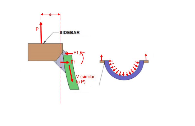
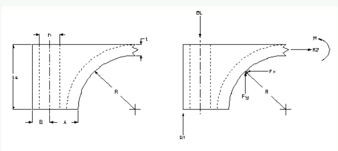
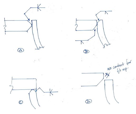
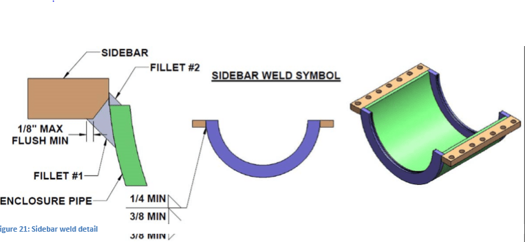
Im needing help with developing some calculations for bending and shear stress. The weld will consist of a partial bevel and a fillet (fillet #2) which joins a piece of flat bar to a piece of pipe. See the picture. This will be used for a bolt-on pressure retaining clamp. Our current calculation method is shown below but I believe it is very conservative. Thanks in advance.

weld_pic_iuobln.png


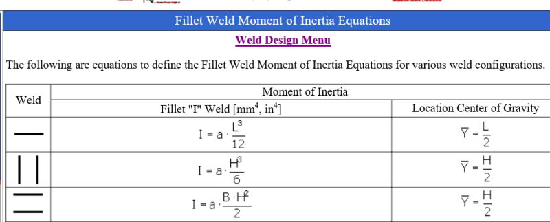
Shear stress = Force / (length of weld) x (Fillet size)
Bending stress = [3 X Force X (pipe wall thickness)] / (Length of weld) X (weld thickness)
 
Replies continue below

Recommended for you

Assuming the force is due to bolts in those holes-
Assuming the two halves don't touch on the flange face when the bolts are tightened-
I would check tension in the weld area as P/A at the narrowest cross section,
And check bending stress as Mc/I at the narrowest section of that cross section.
As drawn, the narrowest section appears to be the curved piece, not the weld metal.
 
Your stress should be based on the effective throats of each weld. Not the weld size. (i.e. a fillet weld throat is 0.707 x weld size).

The bending stress should be based on the net reaction pressure force on the bolts times the distance between bolt centerline and center of weld. Not sure what the pipe thickness has to do with this.

Check out Eng-Tips Forum's Policies here:
faq731-376
 
Thanks for the reply. I have other calculations that analyze the stresses in the enclosure pipe and flat bar. I have come across the imagine below for welding I-beams but I'm not sure its the same with my weld configuration.

My concern is making sure the welds are sized correctly.

Some more information.
The pressure would be coming from the internal pressure of the enclosure.
The halves will come together at the split line, metal to metal.

have come across the imagine below for welding I-beams but I'm not sure its the same with my weld configuration.

I_for_weld_shapes_kcr2ya.png


weld_pic_2_cdfvvc.png
 
Those don't appear to have anything to do with what you are doing.
Your weld is experiencing a moment about an axis parallel to the pipe itself so you will have a force couple between your two welds from the eccentricity between your bolt force and the pipe weld centroid.

Weld_bhkyzu.jpg


Check out Eng-Tips Forum's Policies here:
faq731-376
 
I'm going to need some more help setting up this formula.

Questions?
1. For bending stress, does the fillet add any strength or should I only consider the bevel?
2. What am I using for my moment of inertia?
Bevel weld throat = b x weld length = d
I=bd^3 / 12
3. What would you call the centroid? The center of the Bevel?
4. Do you agree with the picture and formula below for setting up my force on the weld? I know this is no representative of the pipe assembly but the idea is the same.

P = internal pressure from cavity
A = edge of flat bar to bolt CL
B = cavity to bolt CL
W = shell wall.

Force on weld = P x [A + B - (W/2)] / 2

bolt_load_mqu7tz.png
 
I think you are confused here. There is no bending in the weld lines along the pipe/bar interface. They are taking direct shear perpendicular to the weld axis and they are taking direct coupling forces perpendicular to the axis as well. Using weld moments of inertia imply that there is bending in the welds resulting in variable stress in the welds along their lines. I don't see that - it is simply a direct, but eccentric, force across the the weld line presenting a uniform stress along the line.

Check out Eng-Tips Forum's Policies here:
faq731-376
 
I'm definitely confused. HAHA

That being said. Is this the better way to look at it?

Weld Allowable Stress = Weld throat X Weld Length X Efficiency X Allowable Strength

Load adding on Weld

Case A = P x [A + B - (W/2)] / 2
Case A is trying to take into account the position of the bolt.

Case B = Pressure area X Pressure
 
I don't like your weld detail here. The way you have it drawn, there is no contact for fit-up - you would need backing bar to start your fillet weld. In addition, your weld is heavily unbalanced, and weld distortion could be a problem. What is the scale of this thing, how thick are the plates? I'd prefer options A, B, or C shown below.

As far as the weld design goes, I agree with JAE's approach.


pipe_weld_von5ws.jpg
 
Status
Not open for further replies.

Part and Inventory Search

Sponsor