Tek-Tips is the largest IT community on the Internet today!

Members share and learn making Tek-Tips Forums the best source of peer-reviewed technical information on the Internet!

  • Congratulations JAE on being selected by the Eng-Tips community for having the most helpful posts in the forums last week. Way to Go!

Weird one.. effective length?

Status
Not open for further replies.

MIStructE_IRE

Structural
Joined
Sep 23, 2018
Messages
816
Location
IE
Hi,

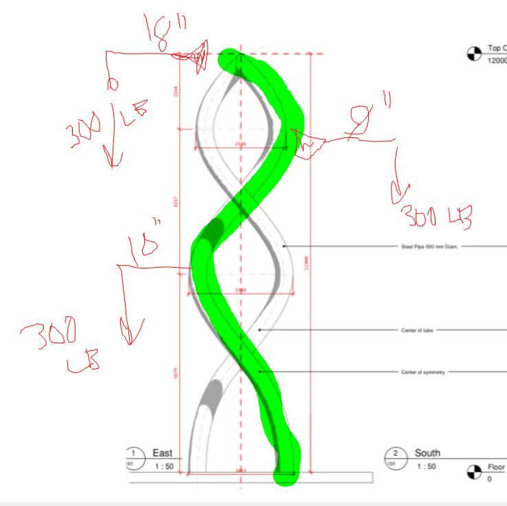
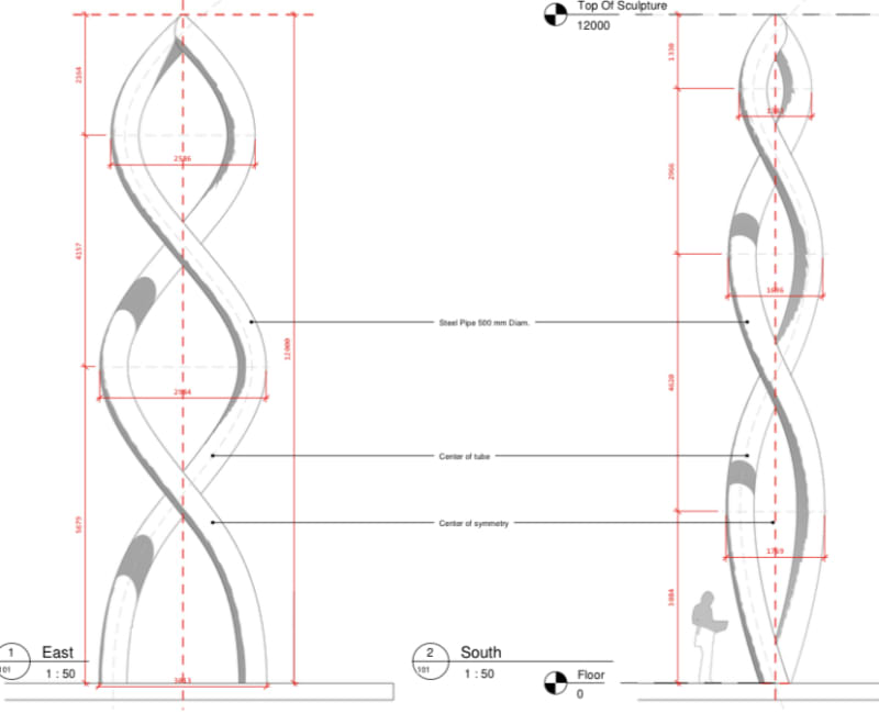
I have an unusual spiral sculpture as shown here. Its fixed at the base and cantilevers up 12m as a double curvature pair of spirals which only connect to each other at the top.

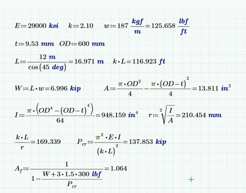
Its mainly taking wind + self weight and snow etc, plus the inevitable teenagers trying to climb it! In terms of effective length, I’m initially thinking of taking the ‘straightened’ length of one of the spirals - unless anyone has a better idea?

It will be subject to axial load, biaxial bending and some torsion. My initial feeling is to use a circular hollow section to at least sort my LTB woes..

718DE426-9EE0-4B1C-B13A-144109BCFB52_btavsd.jpg
 
In a way it's already hinting at its buckled shape. Definitely a mind bender... cool project!
 
sure developed length, but if you're looking at column allowable ... what sort of load eccentricity would you use ?

if you pin the base, then each spiral is "just" a two force member, maybe 3 force member if you include weight.

if you could tie the two spirals together with narrow wires (like DNA) that would make the structure very stable.

another day in paradise, or is paradise one day closer ?
 
Thanks Guys, yeah I’m considering some light wire ties at maybe 3-4 points.. Not sure if I really need them though, but I’d feel better if I could get them in!

I’ve analysed the “frame” without them and now have a feel for the magnitude of the moments and axial compression. The remaining question is what effective length I apply this to though.
 
I like FEM buckling analysis for this as it's likely to be one of those situations where the effort will truly get you a nice, light design that you can have confidence in. I'd model one noodle on its own and check out some lateral and torsional buckling modes. But, yeah, if there were no such thing as computers, I feel that K=2.0 on a straightened out noodle with load eccentricity would be sensible.

C01_xorkm6.jpg
 
Thanks Koot, yes I think we’re on the same page.

Much appreciated all.
 
You could run direct analysis on it as per the US code (AISC 360) It's a small-enough structure just to lean it slightly in two directions and lower the E stiffness. If compression buckling is really an issue, this will give you an improved estimate of the foundation reaction as well as the structure design.
 
This is FEA all the way IMO. Question is what level of FEA is sufficient. Beam model with small straight segments that approximate the centerline of the shape? A shell model in Abaqus or similar with linear eigen value solution, or a full non-linear solution with initial imperfections?

My vote is for a shell model with a linear buckling solution, since the shape is already a bit imperfect (not very straight!), but I can see the argument for a beam model as well with each segment treated as a beam-column.

“The most successful people in life are the ones who ask questions. They’re always learning. They’re always growing. They’re always pushing.” Robert Kiyosaki
 
I find it hard to believe axial buckling is even that relevant. It's only its own self weight right, and judging by the size relative to the person, it's very stocky.

Am I missing something?

Other load effects are probably more relevant.
 
Buckling won’t be critical. Check the section as a straight pole under self weight with K=2.0 if you’re concerned. Buckling under self weight is half as bad as all the load at the tip (work integral of S/W is a triangle as opposed to a rectangle)
 
I did a some conservative ballparking on this and the other guys' instincts are sound; it appears that axial will be of little significance. Even at kL = 117 ft and KL/r = 170, the available axial capacity is vastly in excess of the self weight or any realistic applied loads such as ice or surly teenagers. A rough moment amplification factor comes in at only 6%. For interest's sake, I've also included the Timoshenko solution for self weight buckling below although I didn't bother to run any numbers on it.

As far as any code based beam-column check goes, it should be relatively insensitive to the choice of [k].

c03_kzlkup.jpg

C01_wkplgy.jpg

c02_zx9urk.jpg
 
Status
Not open for further replies.

Part and Inventory Search

Sponsor

Back
Top