Continue to Site

Eng-Tips is the largest engineering community on the Internet

Intelligent Work Forums for Engineering Professionals

  • Congratulations waross on being selected by the Eng-Tips community for having the most helpful posts in the forums last week. Way to Go!

VERY Thin-Walled Tube Design

Status
Not open for further replies.

1SEngineer

Structural
Aug 27, 2007
37
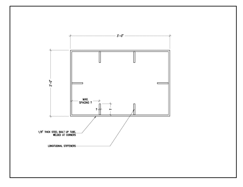
I'm working on a very unorthodox design that requires the use of 1/8" steel plate to create large tubular sections. The plate will be cut from sheet and welded at the corners of the box. The rectangular dimensions vary quite a bit. I have attached a sketch of one of the larger shapes...which is 24"x36". We are trying to using the 1/8" walled tubes as a structural element to eliminate the cost of heavier steel "bones".

So...

1) Can I...and/or should I...use longitudinal stiffeners to reduce b/t to acceptable AISC limtis? I should then be able to use standard HSS design criteria once the section is stiffened.

2) Where can I find information on designing the stiffeners? (I have been directed to NACA Technical Papers...but not being too familiar with these...I've decided to give EngTips a go. Perhaps someone can abbreviate my search.)

3) Or...perhaps someone can offer another economical solution?

Thanks in advance for any help!


BoxSectionSketch_sykcuy.jpg
 
Replies continue below

Recommended for you

Have you looked at the AISI documents? I forget what the max thickness of steel is that applies to them, but this seems like a problem that is similar to what it covers.
 
It's been a while since I used it, but in the appendix of AISC-ASD 9th Edition, there are provisions for thin sections like this; I assume similar provisions are in the newer version as well. If you can omit the stiffeners, the design is simplified considerably.
 
Blodgett's got some stuff on this:

Link
Link

I feel as though horizontal stiffeners might be a better way to go. They wouldn't need to span nearly as far.

I like to debate structural engineering theory -- a lot. If I challenge you on something, know that I'm doing so because I respect your opinion enough to either change it or adopt it.
 
Unless each section (how long is each section?
how many sections total will be assembled together?
What racking (twisting axially) are present?
What tension load is present, and is there ANY chance that tension load could become compressive?
How are the sections fastened together?

I am afraid this tube-like structure will twist and rack, the sides will flex up-and-down, in-and-out (left/right) under low forces, and the assembly will likely fail under even low loads unless each 2x3 foot section is either very short, or fastened securely to a very stiff assembly above and below it, or is fastened to each adjoining member by a very stiff flange-type structure.

To fabricate, I'd recommend bending each 1/4 plate into an L-shape, then welding the internal stiffeners inside the L while in a jig or fixture. Then, paint the internal and external with the two matching corners taped off, then weld the corners to each other with outside welds.
 
I did my university thesis on cold-formed steel structures - specifically optimising a channel cross section for axial/bending forces.

Anyway, you may understand the behavior of this cross section a little better if you model it using the program CUFSM Link

Then use the Direct Strength Method to determine capacities and check sensitivity of various stiffener arrangements.

 
what is the loading?.....what is the length?......horiz stiffeners would be more effective @ maintaining the overall rectangular shape....
 
All,

Thanks for your comments.

My responses:

njlutzwe: After researching this further...I feel that this is the best route to take. Interestingly...I already have the 2001 Edition of AISI. I haven't used it in years. Bought for another project...way back. So...I've read through it...and I do think that this should suffice. It has numerous conditions for finding effective width...and formulas for stiffer size and spacing. Now...I'll have to convert all this to an Excel spreadsheet...fun...fun. Thanks for the tip.

JStephen: Yeah...I looked in the 14th Edition...and it has information on slender elements in the commentary. It actually references AISI standards (see above)...hence my decision to just go with the AISI spec.

KootK: Blodget...yeah...I didn't think of his books. Thanks for the links. Yeah...I've thought about horizontal stiffeners as well. However...I'm not sure how to run numbers on that orientation. (I don't recall seeing horizontal stiffener design in the AISI spec.) I may incorporate them at specific areas...to stiffen the skin further. So...I think the longitudinal stiffeners should be the main stiffening element...and horizontal stiffeners could be supplementary.

racookpe1978: This structure is actually a large sculpture. The tubular sections vary in size. The tube will be built-up from 1/8" plate. It will be welded at the corners. The tube sections will be as long as 20 feet. There will be bi-axial bending as well as torsion...and axial loading...of course. There shouldn't be much racking (no seismic)...but the cross sections will see tension & compression...depending on the direction of wind pressures. The sections will be welded together. Yes...buckling will be likely if the cross section is not stiffened properly. Also...know that the only loading on this structure is self weight and wind forces.

Trenno: Thanks. I had a look at the website...but haven't had the time yet to download the software. This may come in handy. I actually try to do FEA with my RISA software...to get an idea of how the plates will buckle under different loading conditions. Unfortunately...the program kept crashing due to the number of elements. So...I will definelety look inf=to the program.

SAIL3: Well...the lengths and cross sections vary. But...it's about 20 feet high...and it is not perfectly vertical. It will be fixed at the base. Yeah...I really have to incorporate horizontal stiffeners.


I appreciate your comments. I'm moving forward with the design using the AISI spec. I hope to also use the FEA program mentioned by Trenno. I'll try to post an update once the design is further along.

Thanks!


There will likely be some welding warpage and welds will be visible on the opposite sides of the sheets. Since this is a sculpture, the artist should be aware of this.
 
Status
Not open for further replies.

Part and Inventory Search

Sponsor