Continue to Site

Eng-Tips is the largest engineering community on the Internet

Intelligent Work Forums for Engineering Professionals

  • Congratulations waross on being selected by the Eng-Tips community for having the most helpful posts in the forums last week. Way to Go!

Verify a water tank capacity 2

Status
Not open for further replies.

Mussif07

Civil/Environmental
Oct 15, 2018
8
Hi everybody,
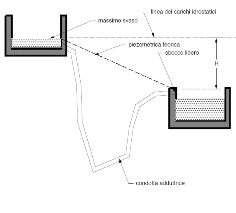
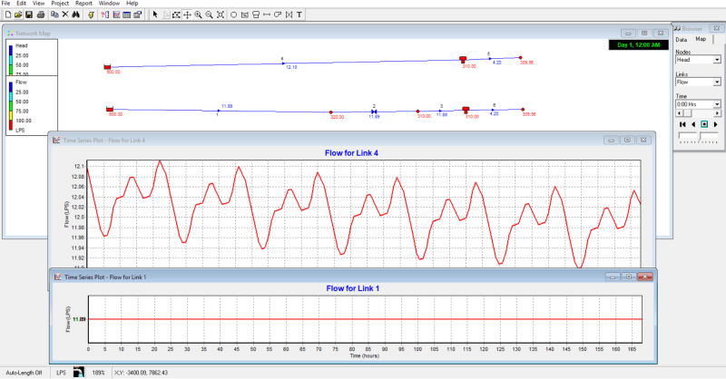
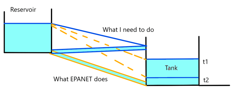
I have been given the task to analyze the behaviour of a storage tank with the predicted populaton at year 2048. Since it is the first time that I face such a problem I decided to try the free software EPANET to evaluate how the tank's volume changes in time(due to a demand pattern). I followed some tutorials to build a simple model with just one pipe connecting a reservoir and a tank but now I'm stuck because I need to mantain constant the Hydraulic Grade Line (so that there is a constant flow between the reservoir and the tank), because the actual pipe is attached higher than the maximum level allowed in the tank. As far as I understand EPANET builds the HGL always connecting the two water surfaces, is there a way to tell EPANET that the pipe delivers water higher than the tank's water surface instead of the bottom level?
I made this sketch to better explain the problem:
Senza_titolo_of1ptx.png


Thanks for your help, best regards.
 
Replies continue below

Recommended for you

Hi gerhardl, tank you for the advice.
My objective is to perform an extended period simulation. I have only an element reservoir and an element tank connected with a pipe.
The element tank is modeled assigning all the parameters: diameter, initial level, minimum and maximum level.
Steady State Simulation:
I connect a junction downstream the element tank to which assign the mean demand (a constant value) of an urban centre in the day of maximum consumption. I connect the reservoir with the tank, run simulation and I get a constant flow in the pipe with the same value that is assigned to the junction. So the demand is satisfied.
Extend period simulation:
Now I assign to the junction a demand pattern to modify the constant flow assigned before (this represents the demand trend during a day). I assign all the parameters to perform a 24 hrs simulation. At this point the tank begins to fill / empty.
It happens that the flow entering the tank stays no more constant, because it varies in time with the water level inside the tank, which depends on the exiting flow (the demand pattern).
My problem is that I want to assign a constant flow (flow in the day of maximum consumption) as input to the tank, and that is not influenced by the application of a demand pattern downstream. I mean that I want to model the system fixing the delivery height of the tank's gateway, so that the HGL in the pipe remains the same as Steady State Simulation, is there a way to do this?
Thanks again.
 
I found a better image of the situation that I'm modelling: do you know if EPANET can represent this particular configuration?
Cattura_xuqigm.png

Tanks again.
 
Just brainstorming... Perhaps a pump with a flat pump curve could be used to provide constant flow rate?

#
 
Adding a pump could be a way, thank you for the advice Pinwards, I was also wandering if a flow control valve (setting its flow equal to the value obtained in the stady state simulation) could help.
But, before introducing elements that does not exist (actually there aren't any pumps and, I guess, there is only a gate valve that opens / closes the water supply), I would rather know if EPANET allows to create a simple model as the one in the picture above. Since I've found in this forum plenty of EPANET threads I was sure to find somebody who could tell me if it could be done with EPANET. To quote Einstein (as my hydraulic professor used to do): "Everything should be made as simple as possible, but no simpler"
 
I would explore at having sensors in the reservoir and tank for water levels of interest in the reservoir and tank and connect sensors to a valve controller that can differentiate the elevations in order to fill the tank. The valve shuts down when the tank level is reached and opens from a partial to full opening depending on the amount of water being drawn out from the tank and the elevation of the water level in the reservoir. The valve controller should be able to modulate the flow rate.
 

If we should solve this by using simplest possible valve solutions, regulated mechanically without electric power or signals, we could do following:

1. Between the tanks, for on off, and at the same time (if necessary, to limit the water flow (if max natural flow situation has to be limited), use a good closeable regulating valve. Use if necessary mechanical limitation at necessary position. Alternative closing and regulating valve in series.

2. For the receiving (downstream) tank: To open the the for receiving flow (inflow)use a mechanical float valve, opening when the water level is at critical low level, adjusted to close inflow when water reaches max/necessary level.

3 For upper (giving tank) either, if necessary, same solution with float valves both for intake or outlet, or if suitable upper level controlled by overflow and/or low level controlled by hight of level placement for outgoing pipe.

4. Simplify input data to EPANET calculation programs by using sensible guesstimates to run control trial calculations for the max, min and medium situations.

All regulations could of course be done electronic and electrically and continously, but it often helps looking at the simple mechanical limitations you have to operate within.


I think you should model a pressure sustaining valve at the inlet to the lower tank, and set the sustain pressure to the HGL of the lower end of the fill pipe. Connect the PSV to the lower tank with a short large diameter pipe. That should allow you to model the hydraulic performance of the supply pipeline, while preserving the performance of the lower tank.
 
As I understand the original problem in the OP, it seems fairly obvious that for the configuration labeled "What I need to do", the tank is irrelevant, as the outflow of the pipe would be unaffected by the level of water in the tank. It could be removed from the model, could it not? If the program cannot model a free outflow, presumably into a drainage ditch, or whatever, then it would appear to be worth about what you paid for it.
 
Producing a constant outflow, unaffected by the level of water in the tank, should be as simple as having the outflow from the pipe enter the tank above the level of water in the tank, restricting the outlet size to the proper cross-sectional area based on the hydraulic head and losses within the pipe. If the pipe enters the tank anywhere below the water level, then where it enters is irrelevant; the hydraulic head is still the difference between the water surfaces in the reservoir and the tank. Friction losses within the pipe aside, it makes no difference where the pipe goes between the reservoir and the tank either, unless it rises above the level of water in the reservoir and it is not kept as a closed system.
 
Thank you so much 77JQX, you put me in the right direction, in fact “PSVs maintain a set pressure at a specific point in the pipe network”.
I haven’t tried on my project yet, but it worked perfectly in this example below, setting the PSV valve to zero and its upstream junction’s elevation equal to the discharge elevation: it is like the inlet is above the water surface: with the valve a constant flow reaches the tank during all over the simulated period.

Cattura_q3v7fi.png


To HotRod10: The tank has the key role to store the water needed to provide outflow higher than inflow…

Thanks to everyone for your hints.
 
Status
Not open for further replies.

Part and Inventory Search

Sponsor