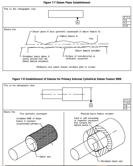
The standard spends a lot of time on types of theoretical geometry derived from different configurations of datum features and where this theoretical geometry is, to the point that I've seen designers think they actually have to point out where a datum axis or center plane is with a leader line and a note. This is really less important, and in most cases arbitrary, (not to mention improper unless in the form of Y14.5-2018 fig 7-56 for a customized DRF) than as I said the relationship between a datum feature and its simulator and how it constrains your degrees of freedom.
Imagine if a bolt circle of 4X holes was datum feature B and a flat perpendicular face was datum feature A. Another feature could be held wrt |A|B| without any concern with where the derived pair of orthogonal datum planes/axes are. Does it coincide at the axis of one of the 4X holes? Is it in the middle of all 4X at the center of your bolt circle/point of symmetry? Who cares - what you're really concerned with is that A constrains (u,v,z) and B constrains (w,x,y). Specifying a unique axis does not change this fact.
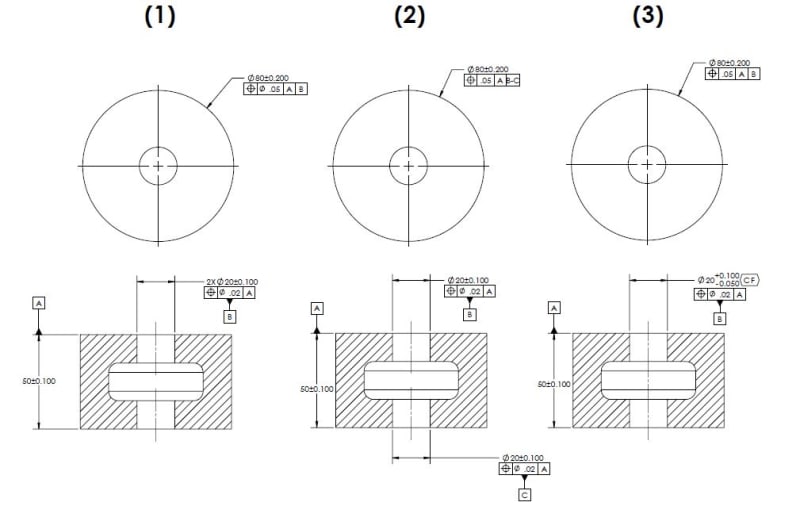
In regards to your options, I'll condense it to the few below - and keep in mind what I said previously that establishing conformance of a feature and simulation as a datum feature are two quite different concepts. Theres a very good reason why the standard differentiates between RFS/MMC/LMC as material modifiers on geometric tolerances and RMB/MMB/LMB as material boundary modifiers on datum feature references.
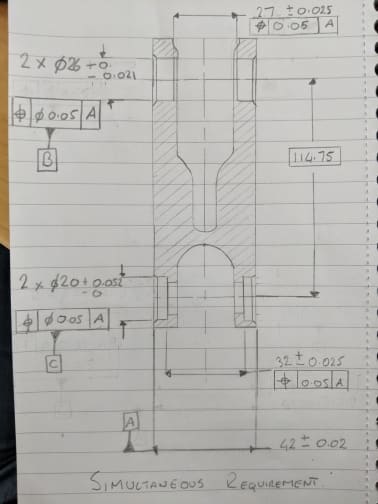
1) 2X pattern of holes specified as datum feature B
2) Each hole individually specified as separate datum features (say B and C) and then referenced B-C
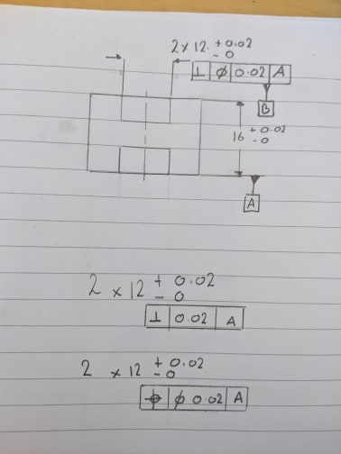
3) The pair of holes controlled with <CF> and specified datum feature B
I believe (1) and (2) result in identical simulators and simulator behavior as specification of the multiple datum feature B-C indicates that both datum features B and C have the same precedence, as if they were a part of a single pattern. Whether or not (3) results in different behavior depends on how one interprets "simultaneous" expansion/contraction of simulators per Y14.5-2018 para 7.12.4 (Y14.5-2009 para 4.12.4), at least for RMB, but I think thats getting lost in the weeds a bit. Even so, for (3) I believe that unless theres a case of extreme size/form error between the features even depending on one's interpretation of "simultaneous" I think the differences in most cases would be very small. Its worth noting that features controlled with <CF>, since they are literally treated as a single feature, do not require (and indeed I believe it would nonsensical to apply) a position tolerance to control relative coaxiality.*
*Edit - I should clarify this, a position tolerance may certainly be applied (as I did in the example in my later post) but it not longer limits coaxiality of the 2x holes since they are considered one (albeit interrupted) feature.