D
duece9s
Guest
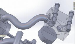
Hi everyone. i am trying to take a 3d sketch from an assembly to make a part from doing a swept profile. i started the 3d sketch by adding points in in the center of the intake ports on both sides (the circle) . Once i had the 3d sketch done i copied the sketch to a new part and started the straight section at the end with a weldment. Then doing a sweep with the weldment profile as the swept profile and the 3d sketch as the path profile, but as you can see its not translating correctly. the top line is the 3d sketch from assembly and the bottom line is the path from the part itself. have tried doing both sweep and loft and it acts the same.
View attachment 1225
View attachment 1225