Continue to Site

Eng-Tips is the largest engineering community on the Internet

Intelligent Work Forums for Engineering Professionals

  • Congratulations KootK on being selected by the Eng-Tips community for having the most helpful posts in the forums last week. Way to Go!

Unique rack an pinion system with fixed and movable rack

Status
Not open for further replies.

greycloud

Mechanical
Apr 18, 2014
127
Hi

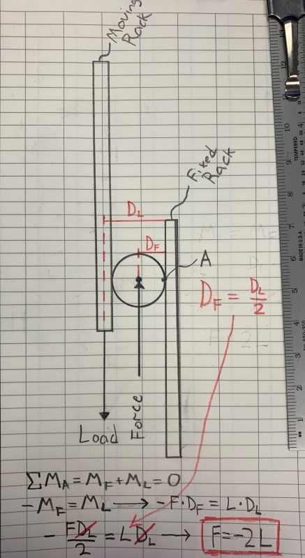
There is a special rack and pinion system that uses pinion travel along a fixed rack to drive a second rack coupled to it for double the distance and hence double the speed.In other words the movable rack will travel double the distance that is traveled by the pinion.Now as per my calculations it doesn't seem this mechanism causes any increase or decrease in torque applied but I would like a second opinion on this. I attached a drawing of system for clarification.

I'm thankful for sharing your thoughts.

Regards
 
 https://files.engineering.com/getfile.aspx?folder=c0bf5e2b-27bb-4114-b38e-d48c387d21de&file=scan0012.pdf
Replies continue below

Recommended for you

For a rack and pinion moving a load vertically, if you have a load attached to either the second rack or the pinion stage itself (in a case without the second rack) that load would be moved twice as far with the load attached to the second rack for a given number of turns of the pinion gear. The potential energy of the case with the second rack is twice as much as that for a single rack and pinion so it required twice as much energy to get there.

Neglecting weight of the rack and pinion components and any additional frictional losses.

From an FBD perspective, the difference is the weight of the load acting on the axis of the pinion or acting at the gear radius so when you sum the moments about the pinion axis it will double the torque required.
 
Thanks for your response.

my actual interest here is in torque required to move second rack. I did a FBD and fund the torque required to be the same since pinion radius is the same between both racks. meaning force of load on moving rack will be the same as force moving the pinion.

allow me to show you and please correct me if I'm missing something. excuse my bad drawing skills.
 
 https://files.engineering.com/getfile.aspx?folder=c761f079-fea9-43a9-b171-882994eb9c6f&file=scan0010.pdf
There are two loads on the pinion, both acting counter clockwise, so a 2X 200 N-m = 400 N-m of torque and it will take 400N vertical force to support the pinion pivot.

If the pivot of the pinion was fixed, there would be only the 200 N-m torque on it from one rack and 200 N vertical force to support it.
 
in the example I'm giving in my FBD there is one load acting downward on Movable rack. how does this translate into two loads? the movable rack induces torque which when divided by distance between pinion pivot and fixed rack will produce downward motion in pivot; since distance between pivot and both racks is equal the force induced in pivot should be same as force acting on Moving rack.

atleast that is how I see it; is their a flaw in my analysis?
 
Each rack is applying a load to the pinion and they must be added. Two loads with a lever arm equal to the pinion radius.

Another way to look at this is that the moving rack is applying a load to the pinion, which then pivots on the stationary rack. In this case you can look at it as one applied load but the lever arm is the pinion diameter rather than the radius.
 
How can the fixed rack apply load to the pinion when its stationary?

the way I see it torque induced in the pinion transforms into downward force due to interaction with fixed rack. in other words fixed rack only helps pinion convert torque into force but it doesn't apply any force on its own.
 
Stationary is a relative term. If you wish to consider the fixed rack as your frame of reference, then you analyze it the second way I mentioned above. If you take the pinion as your frame of reference, you use the first method. You could also use an energy method to to analyze what is happening. Work is force times distance and energy must be conserved. You cannot switch frame of reference in the middle of an analysis.

We cannot explain it any clearer than this. Now it is up to you to understand.

As for "How can the fixed rack apply load to the pinion when its stationary?" Try to remove the fixed rack and see what happens. What do you think it is doing?
 
Look at the pinion and its interactions with the racks on either side. The center of the pinion's shaft (where the force is applied) and the two contact points on either side are literally a class 3 lever.

This applies if the assembly is static, and disregarding additional forces due to accelerations of the components, at any 'snapshot' during movement.

1_m5r85c.jpg
 
Thanks alot jgKRI for the good explanation and drawing. I can see my mistake very clearly right now.

My major mistake is I applied the moment created by force on moving rack around the pinion center; while the actual moment was created about interaction point between pinion and fixed rack.


Status
Not open for further replies.

Part and Inventory Search

Sponsor