Continue to Site

Eng-Tips is the largest engineering community on the Internet

Intelligent Work Forums for Engineering Professionals

  • Congratulations cowski on being selected by the Eng-Tips community for having the most helpful posts in the forums last week. Way to Go!

Uniformly heated drum, NOT! 1

Status
Not open for further replies.

itsmoked

Electrical
Feb 18, 2005
19,114
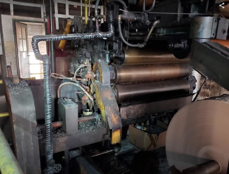
I'm working on a large machine that has an oil heated drum that runs partially submerged in tar.

This is essentially what it looks like and how it's currently built.

Dimensions are not exact and are in feet. (About 8 feet long)

Oil_heater_qenerv.jpg


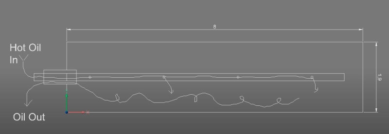
As depicted they pump 250F° oil into the center pipe.
The pipe has a few hole pairs drilled 180° apart on the center in-feed pipe.
The oil leaves the drum out the end as shown.


Looking at this I think it really can't work very well because of the lack of pressure control on the oil, poor flow rate control, and probably lousy flow sharing by all the holes.

They've dissembled the drum looking for clogs or gunk and there has not been any.

They are complaining that the surface temperature of the tar soaked surface is all over the place varying by more than 70F° in various poorly defined regions. This is causing the laminating process to be.... sub par..

Is there a more modern standard way to be doing this that provides a modicum of uniformity? Maybe a single eductor at the end of the in-feed pipe? Or ?


Keith Cress
kcress -
 
Replies continue below

Recommended for you

So, just to clarify, they want the surface of the drum to be a consistent temperature?

How big are the holes? Is there any data on how much of the feed oil is exiting any of the holes? Is the filling of the drum with oil for thermal mass/stability?

TTFN (ta ta for now)
I can do absolutely anything. I'm an expert! faq731-376 forum1529 Entire Forum list
 
That is not an unusual design for an oil-heated roll, although most will have an inner cylinder with spiral flow channels to get better heat transfer to the outer surface, by increasing flow velocity and flushing of air inside the roller. It also reduces the volume of oil in the roller. The main considerations are the heat load on the roller and the rotational speed of the roller. Rotation of the roller mixes the oil and reduces the influence of natural convection, which tends to heat the top of the roller more than the bottom. If the roller is not rotating all the time, the shape can become distorted due to uneven temperature.

The biggest draw back to oil heat is that it can transfer only sensible heat (no latent heat). That means that any heat drawn from the oil to heat the roller results in a proportionate drop in oil temperature, which means that temperature of the roller cannot be uniform. High oil flow rate is necessary to minimize this effect. Having the oil enter and leave from the same end greatly restricts the flow of oil. Other sources of heat to the process can be used to minimize the heat load on the roller.

Steam heat is much better at transferring large amounts of heat and maintaining a uniform temperature. One pound of water will deliver one Btu per degree F of temperature change. One pound of steam can deliver about 900 Btu with no temperature change. To convert that roller over to steam would require changing the rotary union for the service and removing the condensate through the center pipe, which would be curved down to the bottom of the roller.
 
So, just to clarify, they want the surface of the drum to be a consistent temperature?

Yes as the temp sets the thickness of the tar. Hence different thicknesses all over a single laminate web due to the temp variations.

How big are the holes?

About a quarter inch.

Is there any data on how much of the feed oil is exiting any of the holes?

None what-so-ever. I don't see any reasonable way to ever get that either since this whole mess is rotating.

Is the filling of the drum with oil for thermal mass/stability?
Not sure what they were considering in the 1050's when someone built this thing.

Good points all Compositepro! I just walked by a new oil heater on 5 pallets costing $120k... No steam at the facility so unfortunately I think that ship has sailed possibly to sink. Dang.


Keith Cress
kcress -
 
Maybe you could build a SDOF transmission line model of the pipe in the middle and the surface of the drum and at least change the orifice size and distribution to try and equalize the surface temperature. Have you got a map of the surface temperature?

Cheers

Greg Locock


New here? Try reading these, they might help FAQ731-376
 
OK, so two likely solutions are:
> incorporating some sort of agitation to increase the consistency of the temperature
> forego the oil fill and have some sort of two-layer counterflow spiral along the circumference

The joule-mass flow must equal the heat lost to the tar, so one simple question that needs to be answered is whether there was sufficient oil flow to start with.

TTFN (ta ta for now)
I can do absolutely anything. I'm an expert! faq731-376 forum1529 Entire Forum list
 
Does the oil recirculate? If so, maybe eliminate the holes to force all the oil to the far end and increase the flow so the delta T is small, thereby insuring temperature gradient is the same as delta T. That's essentially what we used to do with water cooled molds. Trying to balance flow with different sized holes and channels was a nightmare.
 
Seems odd to be partially submerged. How much heat loss is involved with that? Heat rises. How big is the tank the tar is in? Is the tar really a heat sink for the heat from your design?

I agree with Compositpro with using steam instead of oil. It's what the ships that use to run on Bunker C used to turn it in to a usable fluid. Can't get much more like tar than Bunker C available in 380 and 460 centistoke.
 
Getting both flow and mixing is a trick. The holes should be small enough that you will get similar flow out of each. And remember to use the hot viscosity of the oil. If possible having short lines to deliver the hot oil to near the inside surface of the drum to help.

= = = = = = = = = = = = = = = = = = = =
P.E. Metallurgy, consulting work welcomed
 
Whay don´t you use an "u" tube steam heat exchanger? In a refinery in similar situations it works.

luis

 
ok, bit more data needed here:

Oil flowrate?
Temp in?
Temp out?
Rotating speed of the roller?
Inlet pressure?

70F is a huge temp difference - what is temp map?

With enough pressure in the header you should be getting fairly equal flow, but I'm concerned that there isn't one at then end to spray oil at the end plate. This end could get colder

Internal blades to mix it all about would help - either as angled blades or even bars like a washing machine

I would be tempted to block off that first set of holes closest to the exit - too much short circuiting there.

The oil will surely be at a level above the exit hole - your waves look very unlikely unless you've got some big blades in there.

Remember - More details = better answers
Also: If you get a response it's polite to respond to it.
 
Line the ID of the the outer tube with a tube of aluminum to get some axial flow from hot to cold spots.
 
Some good ideas here. The industry standard is hot oil so steam ain't happening. If you look at temperature controlled cylinders the offerings are; hot water, cold water, 'thermal oil'. Steam is an entirely different animal requiring people who understand it.

Various interesting suggestions can not occur because these cylinders tend to be pipe with ends welded in. There is not access except thru the removable inlet/outlet pipe. Adding various directing pipes, mixing paddles, additional walls, and structures can't be done.

Trying to gauge the hole placements and sizes and modifying them, while certainly possible would probably take 6 months of continuous modifications and would only EVER work if the oil temp/pressure/flow was rigidly controlled and fixed. Probably impossible in a facility plumbed with heat-traced oil lines running everywhere servicing multiple machines and processes scattered about the place.

The tar trough is about 50% bigger than the roller and is also oil heated. The roller is simply a transfer device designed to pick up some tar and transfer it to the moving paper web.

LI even if I could get you all that information what would we do with it. I put zero faith in any kind of simulation relating to this thing. I will grant that we should instrument it and perhaps get some control over the flow and track the temperature of the oil accurately.

This machine has got a bunch of push buttons and VFD speed knobs and valves and levers and cranks. I'm going to be required to control all of it with a PLC. I know they're suffering from this roller being badly inconsistent and was hoping to simultaneously 'roll' in an improvement in that regard, while everything else was being updated. ie no additional production delays.

Looks like this won't work as waiting to get it all running to see what the oil flow is like, etc., means it will be considerably harder to get this improved. Once I get everything else running they're going to be desperate to get production running and not start on a roller 'temperature improvement expedition'.


Keith Cress
kcress -
 
If all you have access to is that internal pipe then try some modifications.

I would have a few more but much smaller holes pointing vertically up to spread the initial heat into the roller.

What happens after that is just a bonus as it flows out.

Keep the total square area of the holes less than about 1/3 of the inner pipe area and you will get equal flow so long as you have enough pressure to fill the pipe.

Why would it take 6 months to see the results?

I'm interested in knowing what the rpm of the big roller is though and the residence time of the hot oil.


Remember - More details = better answers
Also: If you get a response it's polite to respond to it.
 
Find some soap and water and wash your hands of this self-inflicted problem they have. It seems like your job ends when they have all the knobs and dials possible to search for a working solution with what they have, but it's their problem they failed to do their job.
 
Why not just directly heat the tank with a propane flame like the road repair contractors do?
 
Just a guess, but I'd bet you a beer that the roller worked for a long time, then somebody with an MBA asked them if they could speed up the line for $'s sake. This may have happened several times until they started producing a crappy product and getting complaints.
 
I'd imagine a thermal camera would be interesting here - to see the heat flow in real time.

"I love deadlines. I love the whooshing noise they make as they go past." Douglas Adams
 
3DDave has a point, my problem is the electrical end.

However, I'm usually the most knowledgeable person on jobs like this and I like to leave things better than before I showed up. I'm there to help not just 'do my job'.

I grill them on how the system is supposed to work. Then I grill them on things that bugged them or made the process chronically problematic. I try to address all those points somehow and then try to mix in aspects where once it's all running I can offer inexpensive improvements like more control of some variable.

One of their pet peeves is the temp gradient over this particular roller.

Heated_roller_kimh2r.jpg


Rob; An excellent idea! I have a FLIR temp camera that I frequently fail to bring in my tool load-out. That would be exceptionally useful for this issue.


Keith Cress
kcress -
 
After turning this over and over it occurs to me the following things:

The introduction of fluid is in the radial center of the cylinder
This fluid is the hottest and therefore the lowest density and viscosity
The cylinder is likely rotating at a high rpm (50 to 100 rpm, maybe higher)
The exhaust is from near the radial center
The fluid is lower conductivity than the metal

In operation, the general motivator is to retain cooled higher density and viscosity oil against the surface of the drum by angular velocity and the related radial acceleration and maintaining a low viscosity, low density layer along the inlet tube creating a short circuit for the hot oil to immediately flow out.

The location of the holes is not important as the Coriolis acceleration will prevent direct impingement and buoyancy will resist outward motion.

It should be a double wall cylinder with a small gap between inner and outer shells and the oil supply and oil drain separated with the oil introduction confined in the gap; it might be better for the oil to be introduced at the axial midpoint and exhausted from the ends.

This would retain the hottest oil against the outer shell where it can carry heat to the tar, be prevented from being removed by buoyancy before that job is done, and prevented from forming an adverse thermal or density gradient.
 
Status
Not open for further replies.

Part and Inventory Search

Sponsor