Continue to Site

Eng-Tips is the largest engineering community on the Internet

Intelligent Work Forums for Engineering Professionals

  • Congratulations waross on being selected by the Eng-Tips community for having the most helpful posts in the forums last week. Way to Go!

Unable to validate FEA model against experimental results

Status
Not open for further replies.

Kimpan

Mechanical
May 30, 2008
39
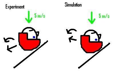
I am performing helmet testing where a helmeted head form is being dropped on an inclined plate. The head form contains 9 accelerometers so that the rotational acceleration can be measured.
The results from the experimental tests are to be used to validate the FEA model I am working with.
The problem I’m having is that the results from the simulations do not match those from the experimental tests. This is apparent when comparing the rotational accelerations from the experiments with those from the simulations. The rotational curve obtained from the experiments stretch over a larger time interval.
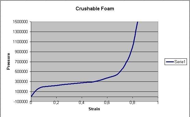
The FEA model consists of the head which is modeled as a rigid interior surrounded by a viscoelastic “rubber-like” material. The helmet is made of a 3cm thick liner of crushable foam and a 0.47cm thin outer shell defined as elastic.
I have performed a parametric study altering the liner density, shell stiffness, friction between helmet and plate. Altering these doesn’t seem to help.

Have I missed something here?
simplehelmparameter.jpg


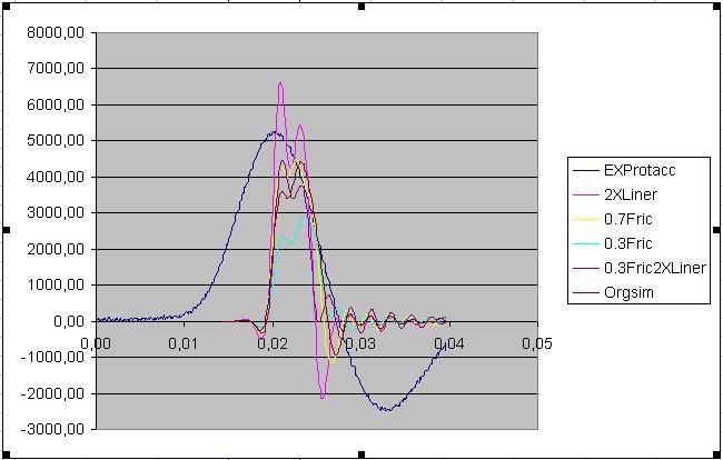
Y-axis is rotational acceleration (rad/sec^2), X-axis is Time (sec).
EXProtacc= The results from the experimental tests
2Xliner= two times stiffer than the original simulation
0.7Fric= 0.7 friction coefficiant between helmet and plate
0.3Fric= 0.3 friction coefficiant between helmet and plate
0.3Fric2XLiner= 0.3 fric coef between plate and helmet and 2 times the density of the liner
Orgsim= The original unaltered simulation
 
Replies continue below

Recommended for you

the colours on the graph don't show up well, but i suspect that the long wavelength curve shows the test results.

clearly, your FEM doesn't match the results, and from your trials there is something fundamentally different between the FEM and the real world.
 
You mention crushable foam and viscoelastic materials but do you have accurate test data for the materials? Are they quasi-static or dynamic? Is this a standard ISO test? I am only familiar with helmet drop tests that slide down a vertical track. Is this for academia or a helmet manufacturer? I hope this helps.

Rob Stupplebeen
 
Your time constants are all wrong, I suggest that your model has insufficient inertia or excess stiffness. BUT the basc form of the curve is very different, implying that you may have a different mechanism completely thwn the test result.

If you integrate all those curves once to get velocity and again to get displacement you may see some more clues. The real result has much greater velocity and rotation.

Try changing inertias and so on.


Cheers

Greg Locock

SIG:please see FAQ731-376 for tips on how to make the best use of Eng-Tips.
 
I should probably explain this some more:
In the experiment the helmeted head is guided by a vertical track towards the inclined plate, so it is a guided freefall.
This is for academia.
I have to agree that there is something fundamentally wrong with the FEA simulation and I think I know what:
I have recorded the experimental tests with high speed camera and it is apparent when comparing the videos with those from the simulation that they are not alike. In the simulations the helmeted head bounces of the plate much more than in the experiments. In the experiments after the impact, the helmet tends to continue roll down the plate. I have illustrated this with a high definition paint drawing down below. Note that the direction of the helmet and head after impact in the simulation is higher than in the experiments.

simexpcomp.jpg


Since the helmet bounces more in the simulation it seems like the frictional force of the plate does not interact with the helmet long enough; the helmet does not rotate as much as in the experiment.
This was clear after comparing the rotational displacement curves of the experimental and simaltion, Thanks for that advice!


The material models of the foam should be accurate, I have reviewed the stress/strain curve and they look legitimate.
How do I get the helmet not to bounce but to rather let the frictional force have its effect?
 
How are you modeling the plate and the supports for the plate?

The "rigid interior" may be a problem.

In the real world, nothing is "rigid", so any such assumptions in a model should be used only with extreme caution.

 
the plate is modeled as rigid and is constrained.
In the real dummy head, the interior is made of aluminum and will not deform. I think it is safe to assume a rigid interior of the head. The helmet will be the one deforming during the impact.
 
I disagree. "the interior is made of aluminum and will not deform" what likely happens is that the interior will deform only a small amount relative to the total system deformation; however the elastic effects may be important to your simulation. But I suspect that the rigid plate assumption may be a large part of your problem. The plate is not rigid; the supports for the plate are not rigid; the elastic effects of the plate and support will likely have an effect on the dynamic response of your system.

I will repeat: nothing in the real world is perfectly rigid. Rigid boundary condition assumptions are very often the cause of simulation errors, especially in a dynamic simulation.
 
I see what you mean, I can try modeling the plate as steel and see if there is any difference but I doubt it. The plate is 1.5cm thick and made of steel. I don't think the elastic effects of the plate will have any real effect on the results. The helmet and head weighs about 5kg and travels at 5 m/s, that will not have a great impact on the steel plate.

Do you mean there will be numerical errors just because the head is modeled as rigid in staid of aluminum?
Looking at the graphs; I doubt the influence of elasticity of the interior of the head and plate are the reasons for the large deviation.
 
How do you model the foam? Does it include viscoelastic effects?
I suspect that the problem is there: the dynamic behavior may be partially viscous (it doesn't recover instantaneously), and a very narrow representation of this phenomenon is required for your simulation.

prex
: Online engineering calculations
: Magnetic brakes for fun rides
: Air bearing pads
 
Hi,
this problem completely falls oputside my range of experience, but...
There are at least two points that come to my mind which can alter FE results wrt experiment for a case like yours:
- viscoelastic materials: very very difficult to correctly simulate their consitutive law within numerical simulations. As this point has already been covered, I will only observ that a "correct" constitutive law will have dramatic importance in the restitution of a "correct" internal damping (your helmet "bounces" more -> it dampens far less)
- unrealistic assumptions of rigidity: if the plate is involved in the impact, it should be obvious that no hypothesis of rigidity can be made on it. It should be modeled with a "correct" constitutive law, and it should be "grounded" with "correct" boundary conditions. Or, in reverse, the experiment should be set up as to "respect" the numerical model as far as possible (ex: is the plate really "rigidly" fixed to "rigid" supports, or the supporting structure is likely to allow for more elasticity / damping?)

In addition, here's another bunch of points related to the numerical simulation: which kind of code are you using? Explicit? Implicit? Is your program able to correctly handle ALL non-linearities involved in your analysis? Is the solver you chose able to manage unsymmetrical problems?
Is the time-stepping appropriate? Which algorythm solves the contact during impact? Is this a Lagrangian one, a Penalty one, a mixed one? Is the time-stepping dynamically adjusted around the impact (i.e. does "impact prediction" controls the time-stepping or not?),... and so on...

Regards
 
Just thinking about it, the KE of the FEA test looks completely different to the real result, I'm guessing somewhere between .25 and .5 times as much. That is a pretty huge error.


Cheers

Greg Locock

SIG:please see FAQ731-376 for tips on how to make the best use of Eng-Tips.
 
thanks for the input. The foam is modeled using the data below and the loading phase follows the stress/strain curve seen in the attached image.
crushablefoam.jpg


RO = 40.0
E= 8000000.0
Poissons ratio = 0
Tensile stress cutoff = 1000000.0
rate sensetivity via damping coefficient= 0.05

I will do a simulation with steel plate and see how that turns out.
 
So you don't represent any viscous effects in the foam. This would result in the stress strain curve following an hysteresis cycle on unloading. However the loading phase wouldn't change much, and you have a big difference already in the first part of the simulation.
Another effect of the viscous behavior is the damping, and I see that you already account for some damping. Try different higher values of damping to see if that helps: the experimental curve appears to be much dampened than the calculations.
I would also concentrate first on the first part of the behavior. Why is it that in the calculation the rotational acceleration is zero over about 20 msec?
Assuming time zero is the first contact, why should there be such a delay? I suppose that examining your assumptions and the model you could find some answers, from here it is difficult to grasp.
BTW are you sure that the experimental and calculated curves are correctly superimposed? I mean: how can you determine exactly a starting time origin that's equivalent for both?

prex
: Online engineering calculations
: Magnetic brakes for fun rides
: Air bearing pads
 
I tried increasing the damping coefficient (0.1,0.2,0.3,0.4,0.5) but it didn’t have any effect on the graphs more than that I could see slight change in the amplitude. The shape of the curve remained the same.
About the time difference: I have just moved the simulation graphs so that they are easy to compare with the experimental graphs. The outputs from the experimental results start recording prior the impact and therefore
This is an explicit analysis performed by LS-DYNA.
 
are there other ways of increasing the damping of the system other than increasing: "rate sensetivity via damping coefficient"?
 
Hi,
hmmm, not familiar with LS-DYNA, but ANSYS (implicit) calls with a similar name a "damping" which has nothing to do with "physical" damping "C" of a structure. It's a numerical solver-related coefficient used to avoid oscillations when solving for dynamics problems.
I suppose you have already verified that you are really entering material-related damping...

Regards
 
Hello everyone,

my first post for a very interesting thread...

at the begining you said that your model bounces much more than in the reality.

with my far mechanical reminds, I will agree that your model for the plate is too rigid and gives back total energy to the helmet until it will absord it itself (that's why so many bounces). On the other side, your helmet model must contains a plastic domain to be more realistic. Which is interesting with cases as this, because the model doesn't consider well the restituted energy, it provocates a bigger restitution... so actually the results are two times far that the reality (I don't know if it clear).

And also, the curve from the accelerometer sounds weird. It's too "curvy", it is well calibrate or dimensionned? you need a time response very short for this kind of experiment.

Actually, I wanted to know where you were about your experimental? Did you solve it?
 
you may not able to "fix" your FEM until you can better explain the testing and FEM curves.

The width of positive pulse of the testing curve can approximately represent the contact time between plate and hat and the negative pulse width represents how "loss" or how "flexible" the rotational connections between hat and head. The high frenquency waves showed in the FEM curves indicate that the rotational vibrations occured between hat and head when it is bounced in the air. Comparing to the FEM curves, there is no high frequency rotational vibrations in testing curve, which indicate that the relative sliding may have occured between hat and head. Otherwise. the overall shear stiffness of the connecting materials for your FEM may be about 5 times higher than the testing material.

Theoretically, rotational acceleration shall disapear immediately after the assembly bounced to the air if the the assemblt is a rigid body (no negative pulse) However, our real world is filled with "integration", "filtering" or "convolution" effects. If the sensors are attached to the hat, the negative pulse is caused by the bounce of the relative rotational deformation between hat and head.

Both impact and contact with friction are difficult things in FEM, not mention the combination of both. I know ADINA can do the contact with friction every well. The difficulty for the impact simulation is that the contact area is very small and stress concentration is extremly high, and therefore is difficult to simulate and estimate the how much energy is dissipated just with one or two elements.

Unlike airplanes or rockets, I don't think FEM is necessary in this case. However, the problem is pretty interesting.
 
Hi
thanks for all the inputs on this problem. I have been busy on other projects so this has kind of been sweeped under the rug as we say in Sweden...
I have in other words not solved the problem yet.

I will comment some of the responses:

"I will agree that your model for the plate is too rigid and gives back total energy to the helmet until it will absord it itself (that's why so many bounces). On the other side, your helmet model must contains a plastic domain to be more realistic."

I don't think the plate is the real problem as I have tried modeling the plate with "iron" material properties without any different results.

The accelerometers were calibrated a weak ago with good results.
I'll post some of the code here if you want to take a look:

Contact between the shell of the helmet (ssid 8010) and the plate (msid 25):

*CONTACT_AUTOMATIC_SURFACE_TO_SURFACE_ID
$# ssid msid sstyp mstyp sboxid mboxid spr mpr
8010 25 3 3
$# fs fd dc vc vdc penchk bt dt
0.500000 0.500000 0.000 0.000 0.000
$# sfs sfm sst mst sfst sfmt fsf vsf
0.000 0.000 0.000 0.000 0.000 0.000 0.000 0.000


Inertia properties of the aluminum head (pid 91)(it is covered by a viscoelastic rubber defined as part 92):

*PART_INERTIA
$# pid secid mid eosid hgid grav adpopt tmid
91 91 91
$# xc yc zc tm ircs nodeid
0.000 0.000 0.000 3.262000 1 4
$# ixx ixy ixz iyy iyz izz
0.017051 0.000 0.000 0.018292 0.000 0.012830
$# vtx vty vtz vrx vry vrz
0.000 0.000 -5.300000
$# xl yl zl xlip ylip zlip cid
0.000 0.000 0.000 0.000 0.000 0.000 101

material properties of viscoelastic rubber surrounding the aluminum head:

*MAT_VISCOELASTIC
$# mid ro bulk g0 gi beta
92 1222.0000 2.1700E+8 1.5500E+6 6.5700E+5 4.940000

Control contact card:


*CONTROL_CONTACT
$# slsfac rwpnal islchk shlthk penopt thkchg orien enmass
1.000000
$# usrstr usrfrc nsbcs interm xpene ssthk ecdt tiedprj
0 0 0 0 0.000 0 0 1
$# sfric dfric edc vfc th th_sf pen_sf
0.000 0.000 0.000 0.000 0.000 0.000 0.000
$# ignore frceng skiprwg outseg spotstp spotdel spothin
0 0 0 0 0 0 0.000
$# isym nserod rwgaps rwgdth rwksf
0 0 0 0.000 1.000000


Status
Not open for further replies.

Part and Inventory Search

Sponsor