Tek-Tips is the largest IT community on the Internet today!

Members share and learn making Tek-Tips Forums the best source of peer-reviewed technical information on the Internet!

  • Congratulations cowski on being selected by the Eng-Tips community for having the most helpful posts in the forums last week. Way to Go!

Type of connection checks

JnT_C

Structural
Joined
Feb 27, 2025
Messages
3
Hi all,

I have a column attaching between two short cantilevered beams and it has been modelled with pinned end connections. Therefore, the connections are only subject to axial and shear loads. When performing detailing checks on this connection, would you recommend following the design example for bolted end plate connections under axial and shear loading (where the column is basically the beam member in the example - AISC Companion Vol. 15 Ex. II.A-11B)?
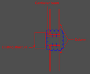
Connection.png
 
You could approach it that way I think.

However, just assuming a pinned connection doesn't make it so. There's rigidity there that will attract moment don't you think?
 
Without knowing more details, I'm assuming you just have tension / compression load from the columns vertically through the wide flange cantilevered beam.

Tension loads across the cantilevered beam can be checked with:
1. Bolt tension - J3.6
2. Check beam flange bending - J10.1
3. Weld from end plate to column - fillet weld calc equation 8-1.

Compression loads across the cantilevered beam can be checked with:
1. Web local yielding - J10-2
2. Web local crippling - J10-3
3. Possibly Web Sidesway buckling - J10-4
4. Web compression buckling - J10-5

If you have shear creating tension or compression on the cantilevered beam, i think you only need to check the bolts for shear.

As mentioned above, just because you modeled it as a pin doesn't mean it will act like one. Use judgement here. Just be logical and follow the load path through the connection.
 

Part and Inventory Search

Sponsor

Back
Top