Continue to Site

Eng-Tips is the largest engineering community on the Internet

Intelligent Work Forums for Engineering Professionals

  • Congratulations cowski on being selected by the Eng-Tips community for having the most helpful posts in the forums last week. Way to Go!

Two Wide Flange Beams Stitch Welded as Column, Torsion Properties 1

Status
Not open for further replies.

jimmyhutmacher

Mechanical
Jan 11, 2011
50
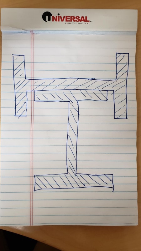
In my industry, fairly tall columns (~50ft) are required with no possibility of bracing and a common style is two wide flange beams stitch welded in a "T" formation as shown below. Required corrosion allowance renders some of these column elements slender as well. It seems that using ASIC 360-16 E7 and E4(b) is correct. A few questions:

Is J = the sum of (b*t^3)/3 accurate with this open built-up section? (Per AICS Design Guide 9)

How do I calculate Cw of the built-up section?

Is there an easy way to calculate the location of the shear center?

1_acgukm.jpg
 
Replies continue below

Recommended for you

I don't know how to approach the nuances of your problem (ensuring they act as a single member for torsional consideration, etc.), but there is a free FEA software that some users here highly recommend. I struggled to install it, but once I figured out the installation and input method, it worked great for me. It can give you pretty much every cross sectional property you could want, including Cw.


I forget who is the expert around here tho. I'm sure they'll show up.

Best of luck!
 
Agent666 is the fellow who introduced us to the software that the Dr mentioned. That would be a good approach but I imagine that you'll want to be able to hand verify the results anyhow.

OP said:
Is J = the sum of (b*t^3)/3 accurate with this open built-up section? (Per AICS Design Guide 9)

I believe that it would be as accurate as in many other situations. It's always an approximation I think. I wouldn't sweat getting too accurate with this as warping stiffness will probably dominate your twist resistance.

OP said:
How do I calculate Cw of the built-up section?

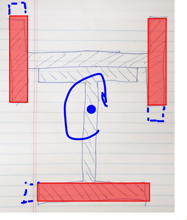
I'd pretend that the section is nothing more than the three flanges shown in the first sketch below to get a reasonable, lower bound estimate. Use that to estimate a center of rotation and then the twist stiffness offered by each flange flexed about its own strong axis. Kinda like shear wall analysis in short buildings.

OP said:
Is there an easy way to calculate the location of the shear center?

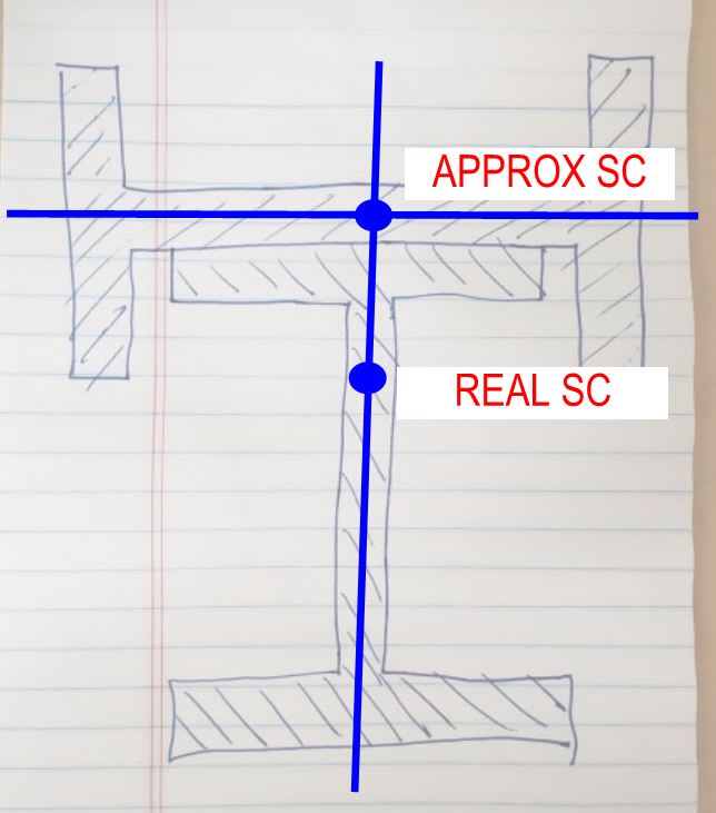
For many purposes, I'd deem it sufficient to plop the SC right along the two strongest lines of flexural resistance in each direction. This one's a bit tricky though in that, depending on what your doing with the shear center, different estimates may be lower bound for different things. Some judgment is required.

With stuff like this, I try not to get too lost in the weeds of mathematical complexity. How you introduce the load to the member at the top and exit the load at the bottom may wall muddy up some of the results of our spiffy math and FEM munching anyhow.

C01_ruh5ql.jpg


c03_xqnld3.jpg
 
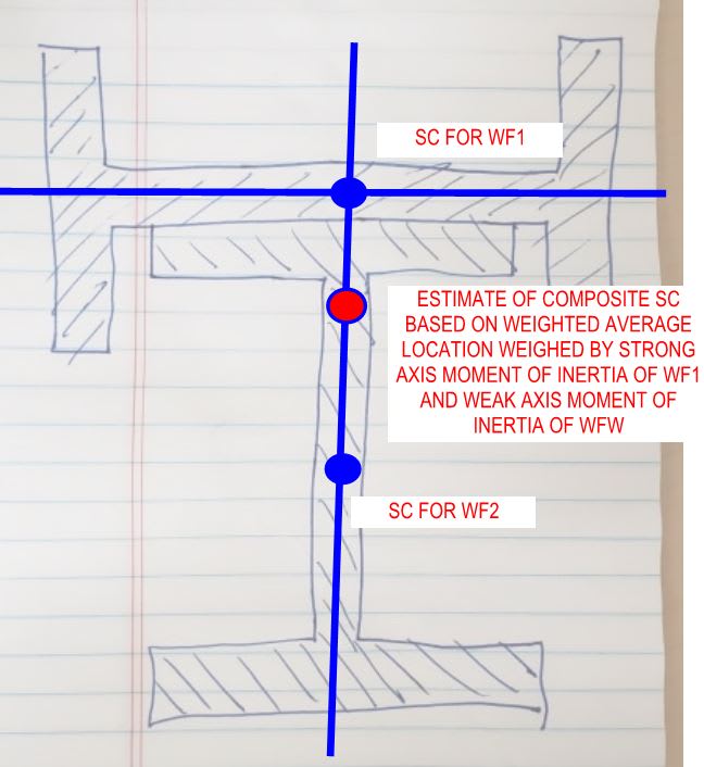
I think that this has merit for the shear center estimate too, although I've probably butchered the explanation.

C01_eqj2gx.jpg
 
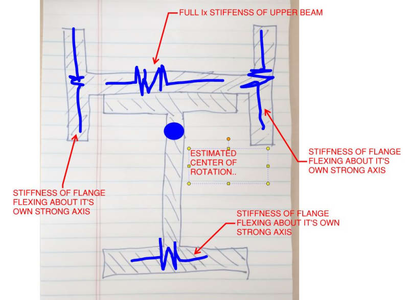
This is probably a better estimate for Cw. It should still be lower bound but stiffer than my previous estimate.

C01_vjvy8n.jpg
 
Adding the J's will almost always be conservative, sometimes overly conservative though, with the true J being many times higher for the resulting composite section. I theorise the reason for this is you are in fact creating a closed section of sorts by welding the two together between the flange and the web of the two sections. Also placing the sections hard against each other in an analysis isn't quite right because they two plates are not connected over the full surface.

I literally just started a series of posts on my personal blog on built up section properties because the subject always seems to pop up here. You might find it of interest.


Here is a script for running with the sectionproperties python package that does exactly what you are after. Just change the inputs to suit.
Python:
import copy
import sectionproperties.pre.sections as sections
from sectionproperties.analysis.cross_section import CrossSection

# -------------------------------------------------------------
# Inputs
# -------------------------------------------------------------

top_flg = False

d = 612  # I-section depth
b_f = 229  # I-section flange width
t_f = 19.6  # I-section flange thickness
t_w = 11.9  # I-section web thickness
r_1 = 14  # I-section root radii

d_1 = 612  # strengthening I-Section depth
b_f1 = 229  # strengthening I-Section flange width
t_f1 = 19.6  # strenghtening I-Section flange thickness
t_w1 = 11.9  # strengthening I-Section web thickness
r_2 = 14  # strengthening I-Section root radii

gap = 0.3  # gap between I-Sections

weld_size = 10  # weld size

n_r = 20  # number of points considered around root radii

mesh_area = 10  # max mesh size

# -------------------------------------------------------------
# Calculations
# -------------------------------------------------------------
# create constituent geometry
# weld base geometry
weld = sections.CustomSection(
    points=[[0, 0], [weld_size, 0], [0, weld_size]], facets=[[0, 1], [1, 2], [2, 0]], holes=[], control_points=[[weld_size / 3, weld_size / 3]]
)
if d_1 > b_f and not gap == 0:
    weld_vert_move = -gap
else:
    weld_vert_move = 0

# I-Section beam
geometry1 = sections.ISection(d=d, b=b_f, t_f=t_f, t_w=t_w, r=r_1, n_r=n_r, shift=[-b_f / 2, -d / 2])

# strengthening I-Section
if top_flg:
    geometry2 = sections.ISection(d=d_1, b=b_f1, t_f=t_f1, t_w=t_w1, r=r_2, n_r=n_r, shift=[-b_f1 / 2, d / 2 - d_1 / 2 + gap + t_w1 / 2])
    geometry2.rotate_section(angle=-90, rot_point=[0, d / 2 + gap + t_w1 / 2])
else:
    geometry2 = sections.ISection(d=d_1, b=b_f1, t_f=t_f1, t_w=t_w1, r=r_2, n_r=n_r, shift=[-b_f1 / 2, -d / 2 - d_1 / 2 - gap - t_w1 / 2])
    geometry2.rotate_section(angle=-90, rot_point=[0, -d / 2 - gap - t_w1 / 2])

# weld 1 & 2
geometry3 = copy.deepcopy(weld)
if b_f > d_1:
    geometry3.mirror_section(axis='x', mirror_point=[0, 0])
geometry3.shift = [min(d_1 / 2, b_f / 2), -d / 2 + weld_vert_move]
geometry3.shift_section()

geometry4 = copy.deepcopy(geometry3)
geometry4.mirror_section(axis='y', mirror_point=[0, 0])

if top_flg:
    geometry3.mirror_section(axis='x', mirror_point=[0, 0])
    geometry4.mirror_section(axis='x', mirror_point=[0, 0])

# total number of individual geometry elements
geo_number = 4

# assemble geometry list
geo_list = [globals()[f'geometry{i}'] for i in range(1, geo_number + 1)]

# create merged section
geometry = sections.MergedSection(geo_list)

# add holes for gaps between I-Section and strengthening tee
if not gap == 0:
    if top_flg:
        geometry.add_hole([0, d / 2 + gap / 2])
    else:
        geometry.add_hole([0, -d / 2 - gap / 2])

# clean geometry
geometry.clean_geometry(verbose=True)

# create mesh
mesh = geometry.create_mesh(mesh_sizes=[mesh_area] * geo_number)

# create section
section = CrossSection(geometry, mesh)

# calculate results
section.calculate_geometric_properties()
section.calculate_plastic_properties()
section.calculate_warping_properties()

# -------------------------------------------------------------
# Display results
# -------------------------------------------------------------
# plot results
section.plot_mesh()
section.plot_centroids()

# display all results
# check [URL unfurl="true"]https://sectionproperties.readthedocs.io/en/latest/rst/post.html[/URL] for definitions
section.display_results(fmt='.3f')
beam_beam_ftlyj3.svg


Happy to run your scenario if you provide the inputs for the script. Otherwise easy to install and run, just follow the instructions on the package page.

 
I've been swamped and haven't had time to look this over yet, but I just wanted to say thank you to DrZoidberWoop, KootK and Agent666! I'll follow up with any questions in the near future.
 
Status
Not open for further replies.

Part and Inventory Search

Sponsor