Tek-Tips is the largest IT community on the Internet today!

Members share and learn making Tek-Tips Forums the best source of peer-reviewed technical information on the Internet!

  • Congratulations TugboatEng on being selected by the Eng-Tips community for having the most helpful posts in the forums last week. Way to Go!

Two Different Flow Coefficients Cd for same Bore

Status
Not open for further replies.

Iomcube

Chemical
Joined
Dec 11, 2015
Messages
187
Location
TR
Following is a picture of an anti-surge device I.e Air Chamber
winhlp32_ZJqi3U1Clu_f7pohb.png


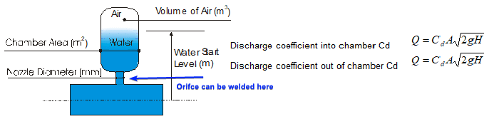
In transient times water can be pushed out of chamber to avoid column separation while high pressure peaks can be cushioned by air volume trapped.

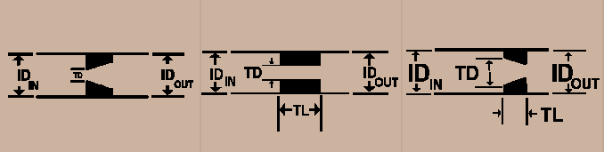
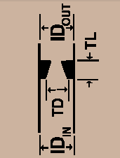
For the flow of water out of chamber I have Cd-A while for flow into the chamber I have Cd-B. Because of the same bore naturally Cd-A = Cd-B

My question now is: Can I have an orifice (or any other arrangement) at the arrowed location such that my objective is met which is Cd-A > Cd-B
 
square edge, round edge and sharp edge orifice, using thick or thin plates all have somewhat different coefficients. If you need a greater difference in directional coefficients, you might investigate installing a reducer or a type of venturi in place of an orifice plate. That would have markedly different directional flow coefficients.

“What I told you was true ... from a certain point of view.” - Obi-Wan Kenobi, "Return of the Jedi"
 
These are the x3 orifice arrangements I know of (flow is always from left to right)

out_hpyiln.png


First is metering arrangement (thin plate), 2nd is restriction (high pressure drop) & third is pressure drop arrangement (metering in reverse with increased thickness)

My understanding is different directional coefficient will be achieved by 1st & 3rd arrangement; with 3rd being the most suited. And if I have installed the 3rd one with small bore facing upward (towards trapped air) like:

kgPnL5QquP_wll1ye.png


I will have Cd-A > Cd-B (at least qualitatively). Is my understanding correct?
NB: For the flow of water out of chamber I have Cd-A while for flow into the chamber I have Cd-B.
 
More or less, but you say "flow is always from left to right". I thought we were doing this because there will be flow into the surge tank and then flow out from the surge tank and you want them to be different in each direction (for the same pressure drop across the orifice).

In the last diagram, upward flow will generate less of a pressure drop across the restriction, than the same flow in a downward direction would generate, as the smaller restriction generates far more of a disruption to flow that extends relatively greater into the smaller flow area there. The conical entrance from below will tend to create smoother flow lines and generate less of a flow disruption. However we(?) don't know what flowrate would occur up, vs the flowrate that would occur down, as that also depends on the (air) pressure in the tank and the liquid pressure in the pipe, all of which in this instance are also functions of time.

Note that there are also pressure loss coefficients associated with the geometry of the opening between the tank and the branch going to the orifice/pipeline and another at the junction of the pipeline and branch going to the orifice/tank. Both of those will also be different for flows going in opposite directions at each respective location. The flowrate into and out from the tank will change as the pressure in the tank changes and eventually equals the pressure in the pipe as any flow through the orifice eventually comes to a halt and then could even reverse ssveral times at that system eventually reaches equilibrium. How accurate of a model do you wish to create?

“What I told you was true ... from a certain point of view.” - Obi-Wan Kenobi, "Return of the Jedi"
 
ax1e said:
More or less, but you say "flow is always from left to right".
Sorry poor choice of words...

ax1e said:
In the last diagram, upward flow will generate less of a pressure drop across the restriction, than the same flow in a downward direction would generate, as the smaller restriction generates far more of a disruption to flow that extends relatively greater into the smaller flow area there.
Recall that through simulation I desire a more restricted flow ingress into chamber compared to egress! Also in the 1st post I have arrowed location where orifice will be place (although your venturi idea is better). Per my understanding what you are saying is opposite to what I understood from my experience. In metering orifices the very 1st arrangement (that is flow entering from small bore side & exiting through larger bore size) is employed to reduce drop & recover most part of it downstream
out_hpyiln.png

This means you have to review this statement:
ax1e said:
The conical entrance from below will tend to create smoother flow lines and generate less of a flow disruption.
...if I have to restrict ingress more than egress
ax1e said:
How accurate of a model do you wish to create?
Not very accurate; but you can say for personal understanding I am generating model
 
Status
Not open for further replies.

Part and Inventory Search

Sponsor

Back
Top