Continue to Site

Eng-Tips is the largest engineering community on the Internet

Intelligent Work Forums for Engineering Professionals

  • Congratulations cowski on being selected by the Eng-Tips community for having the most helpful posts in the forums last week. Way to Go!

Truss Connections with Double Angles

Status
Not open for further replies.

dcStrucEng

Structural
Feb 26, 2009
45
I am detailing steel truss connections and I am having a brain fart about something; hopefully you all can set me straight. I have the truss designed and now I am drafting it, specifically the connections. I started with a truss line diagram (based on my analysis model) then overlaid the members by placing the member centroids on those lines.

The diagonal web members are double angles, L4x4x1/2 to be exact. Their centroids are based on the x-bar and y-bar values in the AISC Steel Construction Manual, which is 1.18 inches from the corner. However, the bolt hole locations are based on the workable gage of the angle, which is 2.5 inches from the corner. Don’t I need to account for this 1.32-inch eccentricity when designing the gusset connection?

Double and single angles are very common web members in trusses. But since the member centroid will rarely coincide with the bolt holes, there will always be an eccentric load when angles are used, won’t there? I’ve always thought that the goal of truss connections is to limit eccentric loading at the connections. But I don’t see how to avoid it with double or single angle members.

If I’m thinking about this all wrong, please let me know.
 
Replies continue below

Recommended for you

Normal practice these days is to shop weld trusses. There is generally more weld specified on the heel of the angles than on the toe, thus dealing with the type eccentricity you are talking about.
 
I think there will be some off-set between the attmt fasteners and the member centroid.

I think you have to follow the loadpath … from the truss member into the connection and then out of the connection into the supporting structure. I think you can apply the truss member load at it's centroid for both locations.

another day in paradise, or is paradise one day closer ?
 
Yes, for the connection design you need to account for the eccentricity into the gusset plate. It should affect the support lengths when calculating your Whitmore section. Sometimes you will see jobs, or fab shops, try to coordinate where the work point is for angles before the design/drafting starts. It can be a lot easier for the connection designer and detailer to use the gauge line on the workpoint but it will impact the design a bit, and vice versa.


...but I can't recall if I have ever solved that problem yet.
 
Some questions for you:

1) what are you using for truss chords?

2) What style of connection will you be using at the panel points?

3) Is this US/ASIC work?

Truss joints are quite often not perfectly concentric for various reasons of practicality. There are a few things that can be done:

4) Depending on the jurisdiction and application, sometimes there are provisions for ignoring small eccentricities. We're making buildings after all, not pianos.

4) You might assume that all of the eccentricity derived moments are taken up by your web members. This usually isn't so bad given that:

a) You've probably already got some moment in your angles about the other axis.

b) I generally think that it's a bit nuts to ever design something for zero eccentricity.

Of course, the joint will likely be an accidental moment connection and the webs may not take all of the moment just because you've asked them to. Chords tend to be stiffer.

5) One might force the webs to take all of the moment via detailing. Make the lead bolt a standard hole and any following bolts short slotted holes perpendicular to the web. This should allow enough rotation in the connection to keep the moments in the webs.

6) Most often, I use rigid offset nodes, as shown below, to capture eccentricity induced moments in the joints.

c01_n9jwmi.jpg


HELP! I'd like your help with a thread that I was forced to move to the business issues section where it will surely be seen by next to nobody that matters to me:
 
Thanks for the feedback thus far. The project is in the US and is in accordance with AISC standards. For this particular truss, the double angle web to gusset connections will be bolted not welded. Although the gussets will likely be shop welded to the chords (WF members). Fortunately, neither the truss member sizes nor the connections need to be efficiently designed, over-designing is perfectly allowed (to a limit, obviously). So the connection can be upsized to accommodate the eccentricity.

But when I turn my attention to the actual detailing of the connection, I had always thought that proper detailing was to align work lines and the intersecting work points based on member centroids. Yet I came across a figure or two (or three) in the AISC Detailing for Steel Construction Manual (digital version is free to members btw!) showing the work line for single/double angle web members being the gage line, as skeletron noted.

While I understand, from a detailing/fabrication perspective, that it makes sense to align the work line with the gage, it's not exactly correct analytically. So I supposed my question to the forum is: should my detailed connections for the double angle web members have work lines being shown as the centroid or as the gage?
 
OP said:
While I understand, from a detailing/fabrication perspective, that it makes sense to align the work line with the gage, it's not exactly correct analytically.

It's your model that's incorrect, not the detailing practice. In my last post, I offered suggestion with respect to what a correct model might look like.

OP said:
should my detailed connections for the double angle web members have work lines being shown as the centroid or as the gage?

I would say that coincident centroids would be best UNLESS there's a practical, fabrication reason to use the workable gauges. And it sounds as though there is such a reason in this case.

You seem to be coming at this assuming that coincident centroids is a hard requirement. It's not. Rather, it's just one of many requirements that will enter into an optimal design including:

- aesthetics
- material efficiency
- fabrication efficiency
- erection issues

An eccentricity free connection is much like a perfect chili recipe: to be striven for, always, but rarely attained. One does not let the perfect chili be the enemy of a good chili.


HELP! I'd like your help with a thread that I was forced to move to the business issues section where it will surely be seen by next to nobody that matters to me:
 
KootK... I'm going to be your cheerleader here before branching onto my own tangent.

KootK said:
b) I generally think that it's a bit nuts to ever design something for zero eccentricity.
Yep. Theory land is great until you get to reality. In reality eccentricity exists, so either model for it or simply be aware where it is significant and where it isn't.

KootK said:
It's your model that's incorrect, not the detailing practice.
Theory land vs reality. Yes some detailing is just poor, but plenty of detailing is just practical and it the the engineering that is asking for the impractical.

KootK said:
An eccentricity free connection is much like a perfect chili recipe: to be striven for, always, but rarely attained. One does not let the perfect chili be the enemy of a good chili.
:)

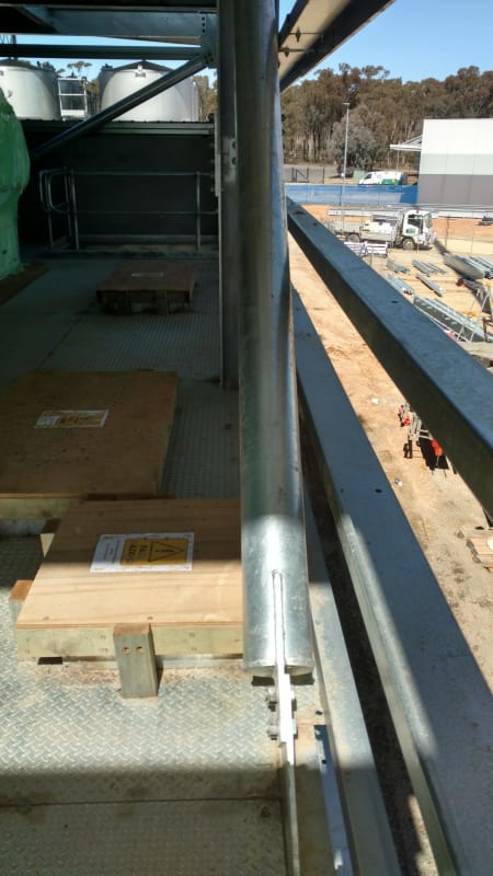
Meanwhile the connections that I see quite often in new structures that scare me a little is hollow connections which fail to account for eccentricity.
This sort of connection:
IMG_20190912_123149473_HDR_rhvhjh.jpg

(12mm plates on 168x4.8 hollow section)

All works well in theory land. But in the real world of eccentricities these connections can fail at much lower values than expected when not allowing for eccentricities.

Either sandwich plates or just thickening up the plates will do the job. (I normally use thick plates), but it is scary when you see fat compression members with weak connections at their ends.
 
I think when you're talking about eccentricity within the connection, there are two things to talk about:

1. Does the geometry of the structure (and relative stiffness of the chords/webs)create the potential for moment transfer through the web to chord connection - do we create eccentricity in the connection? If the work point of the webs is offset from the centroid of the chord then you'll have some eccentricity that must be resolved among the webs and chord (see KootK's diagram above showing the rigid offsets). And if the connection material isn't centered on the centroid of the web, you develop some eccentricity that must be resolved (source of this discussion).

2. Is the connection stiff enough to participate in resisting these eccentricities? Imagine this - you have webs that are all connected with a single bolt at each end. The bolt is located at your practical gauge, which is offset from the centroid. In addition, the web work point is eccentric to the chord. The web to chord connection cannot resist any rotation, but the truss can be stable. The web will bend slightly as the centroid tries to align with the line of action of the bolts, and the chord will bend between the webs as it deals with the eccentricity between web and chord.

The further your connection detail strays from a true pin connection, the more eccentricity you will have to deal with in your connection. There is some engineering judgement in there as to when you have to take a look at the potential for significant eccentricity.

In your particular case, if you have (2) bolts located 2.5" from the corned aligned longitudinally with the member at a 3" pitch, my gut tells me that you're probably close enough to a pin connection to ignore eccentricity with the connection. There is some oversize in the bolt hole and the bolt hole is excepted to deform slightly which will allow more end rotation. Note that is for the design of the bolts - your gusset may still have to be designed to handle some bending so that it can serve as part of the rigid offset shown in KootK's diagram. I would be looking to the uniform force method (UFM) to deal with this.

In an effort to reduce the eccentricity, you could use an unequal leg angle. An L6x4x3/8 has almost the same area as your angle and you could get a bolt very close to the centroid of the section in the 6" leg.
 
human909,
Yes, I think a lot of folks are still ignorant of that mode of failure in strut connections. Another way of dealing with the eccentricity is to provide transverse stiffeners.
 
hokie66 said:
human909,
Yes, I think a lot of folks are still ignorant of that mode of failure in strut connections. Another way of dealing with the eccentricity is to provide transverse stiffeners.
Thanks.

Half the reason for many of my posts, like that one is seeking confirmation or disagreement. Where I work I don't have senior engineers to discuss such aspects with so sometimes. Sometimes reassurance that I'm not crazy is good!

It just boggles my mind that some engineers seem to over design the strut but then do a flimsy connection on the end. It is like that have cognitive dissonance of the structural fores.
 
kootk said:
But in the real world of eccentricities these connections can fail at much lower values than expected when not allowing for eccentricities.
1000% agree, early in my career I was involved in investigating a localised collapse whereby some eccentric cleat connections like you picture failed by buckling in a sway mode as per some of the pictures in the paper you linked to. This failure in a large distribution center involved a long span beam with props from column to underside of beam in an effort to get the beam to span just that little bit further. Workers came into work one morning to find some of the struts end connections buckled sideways and roof just hanging in there. Kicked off a lot of research and testing in NZ & Australia in the early 2000's and subsequent design guidance for these type of connections. Turned out in the failure there were some contributing factors, such as contractor using grade 250 plate instead of the required grade 350, and columns being square hollow sections but oriented at 45 degrees (so become unstable for lateral torsional buckling, compared to a square hollow section located square on, and presence of the strut created moment about this 45 degree line). Notwithstanding these things the designer had not recognised the sway mode of failure, the standard design guide used at the time also had not recognised this dominant failure mode. Cost a lot of time, money and many denials by all parties as to the severity of the situation to rectify the issue.


In my mind the OP's initial issue is usually dealt with as follows in this part of the world:-

For welded connection, align centerline noding based on centroids of angles about that axis/leg. If you cannot node all the angles (verticals/diagonals/chords), then model as per Kootk's advice and deal with the resulting design actions on the chords (and web members).

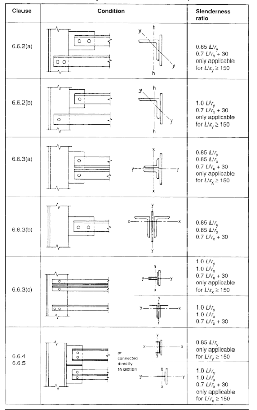
For bolted connections, align centerlines based on angle gauges/bolt group centerlines. Usually for angles in this part of the world (New Zealand), codes modify the slenderness based on the end connection type (see example below). Therefore design of angles directly takes account of the eccentricities involved between the bolt gauge and the centroids, if judged stocky (slenderness less than 150) then we are required to look at the moment and axial interaction for the design of the angles, so offset from bolt gauge to centroid of angle is directly accounted for by the moment induced by this condition. If slenderness is greater than 150 then the modified slenderness is meant to account directly for the effects of moment and axial load. Again if there are eccentricities in the noding of members though, then model appropriately to deal with actions resulting from eccentricities on the chords (and web members).

4_vol316.png


I suspect most standards have similar provisions to deal with these effects. I believe our provisions were originally based on British standards approach. Though I know that Australia who have an almost identical steel standard to New Zealand do not have these same more comprehensive provisions. Your mileage might vary then depending on code. But either way there should be provisions for combined bending/compression & bending/tension that you can apply provided you get a handle on the design actions resulting from the eccentricities involved.

Often small eccentricities lead to small moments, but often around the minor axis of member where capacity is equally proportionally low. So while you could potentially argue them away as being insignificant and small this is often not the case. For example a small minor axis 10kNm moment due to eccentricities, may well use up 10-20% of an I-section members capacity when you back calculate through all the combined actions checks. This is significant and should always be considered in my opinion.
 
Agent666,

I couldn't find where KootK said that in this thread, but it is good advice anyway.

So as not to confuse two issues, the OP was asking about planar eccentricity, and human909 addressed out of plane eccentricity. Both types of eccentricity are of greater consequence for compression members than for tension.

 
hokie66 said:
I couldn't find where KootK said that in this thread, but it is good advice anyway.

Sorry it was Human909! Apologies!
 
hokie66 said:
So as not to confuse two issues, the OP was asking about planar eccentricity, and human909 addressed out of plane eccentricity. Both types of eccentricity are of greater consequence for compression members than for tension.
Yes. I was taking the thread on a different tagent for my own interests. Thanks for clarifying the difference.

Agent666 said:
1000% agree, early in my career I was involved in investigating a localised collapse whereby some eccentric cleat connections like you picture failed by buckling in a sway mode as per some of the pictures in the paper you linked to. This failure in a large distribution center involved a long span beam with props from column to underside of beam in an effort to get the beam to span just that little bit further. Workers came into work one morning to find some of the struts end connections buckled sideways and roof just hanging in there. Kicked off a lot of research and testing in NZ & Australia in the early 2000's and subsequent design guidance for these type of connections.
Good to know the background. I did wonder why the research happened to occur in Australia. I only stumbled across it because I was looking over an external consultant design work and it really seemed odd to have large compression struts finishing with such small eccentric connections. And in this case the compression strut was taking significant gravitational load, not just lateral load from wind/seismic.
 
Thanks for the paper human909. I was not up to speed on that particular issue. In the paper, their dealing with cleats parallel to the strut which simplifies things some. Is there any guidance on how to handle more common configurations like that shown in the photo that you posted? It would seem as though the cleat would get pretty long and that stiffeners etc might be needed as Hokie suggested.

HELP! I'd like your help with a thread that I was forced to move to the business issues section where it will surely be seen by next to nobody that matters to me:
 
human909 said:
I did wonder why the research happened to occur in Australia.

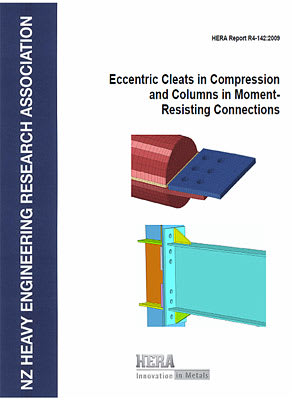
Hera (Heavy Engineering Research Association) in New Zealand did a lot of investigation into it in conjunction with the designer, they produced this guidance which covers an updated design procedure for unstiffened and stiffened eccentric cleat connections:-
R4-142_z44nt4.jpg
 
Beat me to it Agent666. :)

KootK said:
Thanks for the paper human909. I was not up to speed on that particular issue.
You are welcome. As I understand it I have vastly less experience that yourself or many of the other regular people posting here. Glad I could add to the knowledge base.

KootK said:
In the paper, their dealing with cleats parallel to the strut which simplifies things some. Is there any guidance on how to handle more common configurations like that shown in the photo that you posted?
There is better guidance in AUS here:
and here:
ASI Steel Construction Vol 43 No 2

Lots of good stuff in the above. Including referencing the reseach from HERA
Of note, there is recognition to the past (and it seems present) lack of consideration of this in Australia:
"Conventional practice has been to design the bracing cleats for no eccentricity when subject to either tension or compression (see Reference 1). As noted in Section 4, this is not in accordance with AS 4100 Section 9"

KootK said:
It would seem as though the cleat would get pretty long and that stiffeners etc might be needed as Hokie suggested.
Exactly. Though I've generally preferred 'excessively' thick plates as this reduces fabrication costs. That said this approach the plate thickness do become quite thick hence my comment about
excessively' thick. I've used 32mm thick plate for some beefy struts. Sure the guys on site comment how big they are but it is normally cheaper to fabricate than something that requies ~3x more plates and welds.
 
Yeah the old hollow sections "ASI blue book" had no consideration of the sway failure mode, this is what was followed in the failure I specifically noted.

I can tell you there was a large 'oh f**k' moment round the office when it was figured out why the detail I discussed failed. It's something that people had been doing for decades without a thought I guess and there would have been a huge amount of connections out there that may ultimately end up being insufficient.

Fast forward 14 odd years and I'm still pointing it out to engineers who are oblivious to fact that you either need to actually design it correctly for the eccentricities to a recognised design guide that specifically allows for the eccentricities and magnification of moments and all that good second order stuff thats going on, or add sufficient stiffeners to prevent the sway failure mode from occurring (which also requires design to justify).
 
There was some discussion about this on Eng-Tips some 10 years ago, after HERA published its design guide. Just search "HERA" in this forum.
 
Status
Not open for further replies.

Part and Inventory Search

Sponsor