Recon1775
Aerospace
- Jul 24, 2002
- 137
Is there a way to have a circular detail view boundary where in the detail view the boundary is trimmed at only the visible geometry. (Using NX 9)
Example:
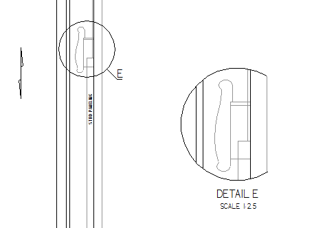
Instead of having the boundary wrap around where no geometry is shown.
As shown here:
Thanks!
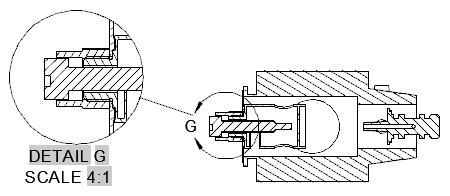
Example:
Instead of having the boundary wrap around where no geometry is shown.
As shown here:
Thanks!
")