Tek-Tips is the largest IT community on the Internet today!

Members share and learn making Tek-Tips Forums the best source of peer-reviewed technical information on the Internet!

  • Congratulations TugboatEng on being selected by the Eng-Tips community for having the most helpful posts in the forums last week. Way to Go!

Transmission Line Geometry and Impedance/Losses

cyriousn

Electrical
Joined
Jul 19, 2017
Messages
33
Location
US
I've recently been building out different geometries in SKM Enhanced Transmission Line Model tool and have been tracking varying reactance values shown below in ohms per mile. For our application we have a 230kv line that travels for a distance of about 11 miles and I'm wondering if anyone knows of any other configurations that may be able to help cut down on the reactance. We are considering option 3A or 3B at this time. Thanks!

1A: H frame single circuit - 0.05443 + j0.76244
1B: H frame (bundled) single circuit - 0.02723 + j0.59044
2A: Single Circuit on Monopole with 2 phases on one side, third phase on the other - 0.05442 + j0.76556
2B: Single Circuit (bundled) on Monopole with 2 phases on one side, third phase on the other - 0.02722 + j0.59363
3A: Single Circuit but split between two sets of conductors, each on a separate side of the pole - 0.02720 + j0.34576
3B: Single Circuit but split between two sets of conductors, each on a separate side of the pole but bundled - 0.01360 + j0.25999
 
6 phase circuit on single tower
So Far only a few installations. Reported to have some advantages in limited rights of way situations.
Revisiting Six-phase Line Transmission

Attached
Performance Evaluation of Six-Phase Power Transmission Line With Limited Right-Of-Way
 

Attachments

We have recently introduced a new class of low-impedance towers, called "5F" and characterized by high Surge Impedance Loading (SIL), low EMFs and reduced Right-of-Way (ROW) requirements. These towers are a specific type of split-phase structure that utilizes 5-conductor bundles.
For a 230 kV line, the reactance is 0.195 Ω/km (at 50 Hz) or 0.376 Ω/mile (at 60 Hz), and the SIL is approximately 300 MW.
Ampacity attains 2500 A (summer rating / 30°C ambient temperature, with our standard 40.5 mm ACSR conductors), corresponding to 1000 MW.
The cost is lower than that of an equivalent double-circuit line or a single circuit split across two conductor sets. The overall height is also less than that of a double-circuit tower.
The first installations are currently underway in mainland Italy and Sardinia, covering several hundred kilometers.

You can find more information at the following links:

(In Italian, but easily translatable with Google Translate):

5phases.jpg5ft.jpg
 
Last edited:
Larger diameter wires, more wires per phase, and tighter phase spacing all reduce impedance. Equilateral triangles will have lower impedance than flat arrangements.
 
Looks like 5 single conductors, not bundles. What's the cost of the transformation between the special 5 phase line and the surrounding 3-phase system? That's got to eat up most of the "savings", the rest of them likely consumed by 5 pole breakers (although that might be an advantage of live tank breakers where everything is single pole all the time). Oddities have their own non-monetary costs as well.

230kV with two conductor bundles would be six conductors instead for the 5 you show, but 3-phase structures instead of 5-phase structures would likely make up for the extra conductor and the spacers.
 
Rather than 5 phase, the 5F tower has a double bundle in the center and single conductors at the edges. Seems like basically two separate circuits with the middle phase mounted on the same insulator. Something like this:

A------B
---CC---
B------A
 
Oh, so spend over 80% of the cost of a two circuit line to end up with a single circuit line? Where NERC's rules around being prepared for the next contingency apply, there's and advantage to having more lines rather than fewer. We're in the process of splitting some superbundles into separate lines just so that one trip takes out 25% of the corridor capacity rather than 50%. The loss of a common structure remains a consideration but given some of the construction I've seen in Europe they must not have to take that into consideration. Having seen structures with two 400kV lines, two 230kV(ish) lines and two or four 115kV(ish) lines they either have way more capacity margin than I'm used to or they don't have to consider the system impact of a single structure failure.
 
Exactly, bacon4life — that’s the phase arrangement.
We call that type of tower “5-phase” because, in IEC overhead line terminology,
“phase (of an AC line): designation of any conductor, or bundle of conductors, of a polyphase AC line which is intended to be energized under normal use”
So in the case of the 230 kV lines in the image, you have four single conductors for the outer phases and a twin bundle for the central phase — totaling five “phases”. The same arrangement is used for 150 kV, whereas for 400 kV you have conductor bundles on all phases.

The system itself is still a standard three-phase system - i.e. no extra cost at terminal station - there are regular three-pole breakers.
As for davidbeach’s comment, there's no universal rule among European TSOs regarding the loss of multiple circuits on the same tower.
In Central Europe (typically in Germany), it’s not uncommon to have four or even more circuits on a single tower — but the loss of all circuits is not considered a single (N-1) contingency.
In Italy instead, the loss of two circuits on the same structure is treated as a single contingency (N-1), so there’s no difference in (N-1) analysis between a double-circuit line and a 5-phases line.
The main benefit of the latter setup is reduced height / visual impact, reduced cost, lower reactance (higher SIL), and significantly lower electromagnetic fields — which is a major concern here, as it dictates the right-of-way (RoW) and, ultimately, the possibility of rebuilding existing OHLs along the same route / RoW while increasing ampacity.
As far as I understand, the OP doesn't need a double circuit, but just a low-reactance line, which could make the cost and ROW advantages of such an arrangement interesting.
 
Last edited:
Interesting, Another difference between IEC and NEC worlds.
Where FPelec describes towers with 5 phases, 1 circuit with unusual conductor arrangement.

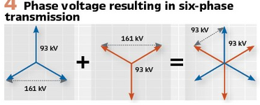
The article I cited above describes a line with 6 phases with 60 incremental degrees phase rotation.
5 phases brings to mind 5 conductors with 72 degree rotation between phases. That would be a seriously complicated transformer winding.

Screenshot from 2025-07-06 06-42-56.png
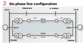
To support N-1 the line could be fed from two transformers - with the line sides 60 degrees offset. These transformers are all made on order, so there should not be much cost difference, and substations likely to be connected to lines like this always have transformers in pairs (at least here).
Screenshot from 2025-07-06 06-44-15.png
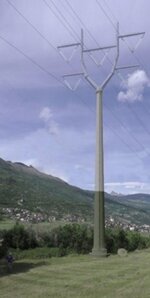
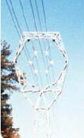
The towers could look like this if the line need to be compact and have minimum possible EMI or conventional 6 poll towers could be used.
Screenshot from 2025-07-06 06-58-12.png
Should lines be circuited this way? Depends on the economics. This must be less costly than under-grounding a line!
 

Part and Inventory Search

Sponsor

Back
Top