Hi all,
This ones confusing me, I'm having trouble understanding how to find the gear train ratio for the following speeds. Hoping someone can help me with a step-by-step explanation.
This ones confusing me, I'm having trouble understanding how to find the gear train ratio for the following speeds. Hoping someone can help me with a step-by-step explanation.
Attachments
-
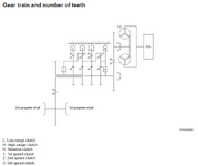 Gear Teeth.png35.8 KB · Views: 10
 -
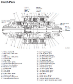 Clutch Packs.png159.5 KB · Views: 12
 -
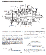 1st speed flow path.png179 KB · Views: 12
 -
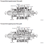 2nd & 3rd speed flow path.png102 KB · Views: 15
 -
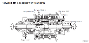 4th speed flow path.png51 KB · Views: 9
 -
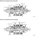 1st & 2nd reverse speed flow path.png102.3 KB · Views: 11
 -
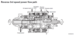 3rd speed reverse flow path.png50.3 KB · Views: 13