Continue to Site

Eng-Tips is the largest engineering community on the Internet

Intelligent Work Forums for Engineering Professionals

  • Congratulations waross on being selected by the Eng-Tips community for having the most helpful posts in the forums last week. Way to Go!

Transfer Structure, which one is better

Status
Not open for further replies.

DisplayName001

Structural
May 10, 2021
9
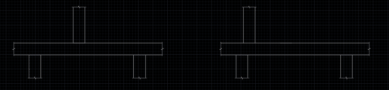
Hi I have questions about transfer structure design. Below is two RC transfer scenarios I have and wondering which one is better and one?
The left hand one I will check the punching shear, which I believe it is critical.
For the right hand one is there anything else that I need to look into in addition to punching shear?
Last question, is there any requirement in regards to the min. slab thickness for the purpose of starter bars for columns below and above?
Thank you


100_hayaap.png
 
Replies continue below

Recommended for you

Will you have conflict issues with your vertical steel reinforcing from the column below to above in the right hand scenario?
 
Thanks for your quick reply.
Can I extend column reo and cog into slab for both above and below one for the right hand side scenario? If no, why can we do this for the left one?
 
I feel that the option on the right is vastly superior as it will transfer much of the load via direct bearing rather than punching shear. This is what I typically see firms do:

1) run the bars through the joint that can run through the joint, checking a mini-column of sorts over the depth of the slab.

2) Hook the bars that cannot pass through the joint at the far side of the slab.

3) Assume that both columns are pinned at the slab for most analysis purposes.
 
Thank you for your help.

In regards to bearing, I find this from the Code. It is Australian one but the concept should be similar.
code_xstrjk.png


I am wondering about How I adopt A1 and N for the right hand side scenario. Please see below my question.
ht_wdsum9.png


If A1 is that red area I mark and N should be used to check the surface bearing, looks like the right hand side one is very easy to fail when the column start to move outside of the zone of the column below (treat it like a moving load) since A1 reduces and there is no way to make it work with given fc. While the punching shear issue on the left hand side can be fixed by either using SSR or drop panel. Can you please explain?


What about the left hand side one with the same connection to slab? I haven't seen people pinned those columns at slabs though. And if you pin those column won't it be aggressive for punching shear check since it has no moments at both direction?

Thank you.
 
I do not think that clause from the Australian code is applicable to your situation. It is more to do with when you have a bearing surface on a pedestal, and depending on the relative size of the pedestal to the bearing area the design bearing stress can be increased due to the confinement provided by the surrounding concrete.
 
Thanks for your reply.

So how do I check the bearing then or I dont have to check the bearing for the right hand side one?
 
So I had a discussion with one of my college today, he reckons that as long as punching shear is checked and passes there is no need to check bearing or strut-tie issue for the offset column shown at RHS above because we are using fcv' when checking punching shear, which is way smaller than fc'. So we can design those two at the same way by simply checking the punching shear.
I cannot tell what is wrong with this opinion. My thought is when we check punching shear we have larger perimeter depending on the slab thickness while this is not the case when we check the strut capacity. What do you think?
 
OP said:
I am wondering about How I adopt A1 and N for the right hand side scenario. Please see below my question.

I think that you could check bearing that way assuming your confinement area to be as large as the slab geometry allows you to. That said, I mostly see people treat the overlap as a reinforced stub column, largely because loads are too high to do otherwise. Granted, the geometry that you've been showing doesn't leave a lot of space for a a reinforced stub column.

OP said:
What about the left hand side one with the same connection to slab? I haven't seen people pinned those columns at slabs though. And if you pin those column won't it be aggressive for punching shear check since it has no moments at both direction?

You would bring your column bars across and hook them, acknowledging that you would really like to have a restrained connection if possible. That said, when column bars do not pass through the joint, it's really a pretty crappy moment connection and that should be acknowledged. One reason to consider strut and tie is that it does acknowledge this.

OP said:
So I had a discussion with one of my college today, he reckons that as long as punching shear is checked and passes there is no need to check bearing or strut-tie issue for the offset column shown at RHS above because we are using fcv' when checking punching shear, which is way smaller than fc'.

The attached sketch is from this thread where this approach was discussed in detail: Link. As you'll note, there's a fair bit to think about there. And, all said and done, I'm sure that a lot of engineers would favor a strut and tie evaluation when there's actually some overlap, as in your case. Frankly, I don't see how you obviate the need for a bearing check regardless of the approach that you take. I feel that turning a blind high to the fact that most of the compression will travel through the overlap is basically just lying to yourself.

C01_fehuua.jpg
 
Status
Not open for further replies.

Part and Inventory Search

Sponsor