Continue to Site

Eng-Tips is the largest engineering community on the Internet

Intelligent Work Forums for Engineering Professionals

  • Congratulations waross on being selected by the Eng-Tips community for having the most helpful posts in the forums last week. Way to Go!

Transfer Beam and Punching Shear 1

Status
Not open for further replies.

Tom_93

Civil/Environmental
Jan 12, 2021
2
Hello,
In my project I have a row of columns, this row of columns should be supported in the beam.
knoten_ppbqws.jpg

My question is,should I consider / check punching shear in transfer beams

Point load = 2700 KN

Beam w / h = 100 / 110cm

Thanks in advance
 
Replies continue below

Recommended for you

What size is the column relative to the beam? Can it punch through? Exaggerated scenario if you had a 200mm x 200mm column sitting on a 2m wide beam - then yes, I’d consider punching.

I’d expect standard line shear will govern anyway if your column is any way reasonably sized.
 
Hello,

the column is circular with diameter =35 cm
 
I can't imagine a scenario where punching shear would govern a beam of those dimensions. Try drawing your failure plane, you end up back at one-way shear plane.
 
I agree that your beam probably isn't wide enough to have to worry about punching shear. That said, it will still be prudent to give some consideration to how effective the beam will be in shear given that the load will be delivered over only part of its width. Historically, firms have deal with the upside down version of this (wide beam over narrow column) in a number of ways. This was studied in 2008 and, in my opinion, the aurthors' recommendations now consitute the state of the art. You can find their recommendations here: Link.

C01_u5lsrj.jpg


c02_tloxfh.jpg
 
I think kootk raises an excellent point that is perhaps not very clearly stated/covered in codes.

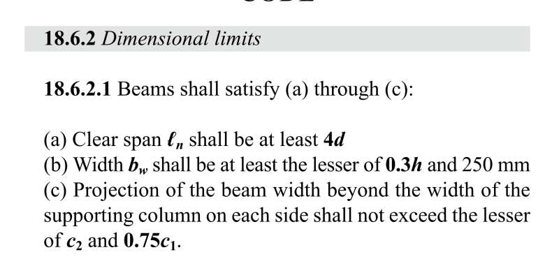
From most codes perspectives they state something like you only have an effective width of a wider beam at the joints and some of a wider beam might be considered ineffective (for both moment and shear). In ACI318-19 this is outlined in part in the dimensional limitations in CL18.6.2 (shown below). But for very wide beams that do not qualify with these provisions the code is a little silent. Clearly it can be wider, but not effective, but the question then is does it act like a two way slab, or other?

So they don't really cover to well is what to do if you want to consider the ineffective width on a wider beam as effective, for example you require the moment capacity of those bars right out on the edge of the beam to be effective, or to get the shear to work you need the full beam width considered and you might not meet the requirements of 18.6.2.

In this case you can use some judgement and detailing to add an orthogonal beam element to effectively pick up the shear from the ineffective part of the beam. In a way sort of like a corbel each side of the column but within the thickness of the beam, depending on the proportions you'd either design using strut and tie or normal flexural theory.

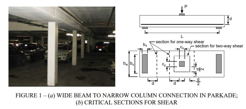
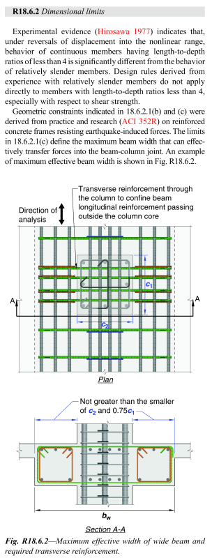
In your situation if you were following the ACI provisions to the letter, then with a circular column if you equated it to a square column of similar area to evaluate the dimensional considerations. Then the max effective beam width would be (1+0.75+0.75) x (π/6*350^2)0.5=775mm. So not all of the beam at 1000mm wide is effective. I'd make sure in this instance that you had sufficient orthogonal bars (and stirrups) through the column core in a similar manner to that shown in the figure below to pick up the shear outside the immediate width of the column (worked out on the basis that it is averaged over the width of the beam). This delivers the load to the column via this orthogonal beam element.

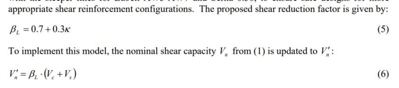
If you're just accepting that some of the beam is ineffective at the support, you need to be careful that you check the max shear provisions based on the effective width. In a way since part of the beam is considered ineffective the shear forces and moments concentrate into a narrower width at the column.

image_xvet1n.png

image_n5pfjz.png
 
Agree with what the others said.

At the end of the day you need a sufficient number of shear legs crossing all potential failure surfaces - be it a 3D punching cone failure surface, or a 2D shear failure plane, or something in between. You don’t want the shear crack being sneaky and getting up and around your shear ties.
 
Agree with Koot on the generation of a perimeter within the beam width for punching shear to apply, which is not possible for the beam dimensions indicated.

Note that Agent666's reference in ACI only applies to beam shear in Special Moment Frames, not Intermediate Moment Frames and would appear to apply to the column supporting the beam, not a transferring column. It appears to be very restrictive for deeper beams such as this one.
 
Rapt, in my opinion the concept is conceptually similar for a transfer column onto transfer beam, just turned upside down. Especially so if you're transferring any considerable moment from/to the column, typically because the transfer beam is stiffer than other beams in a system these poor columns seem to attract a much higher moment for example than others depending on overall system stiffness. If there's one thing you want to ensure is that the transfer elements are fairly robust!

While that ACI clause is in the earthquake part of the code, since nothing exists elsewhere in the code eluding to the potential issues apart from the joints limitation in CL15.4.2.4, I believe you can apply similar logic for gravity cases as you fundamentally have similar behaviour with the load trying to get to the column and an effective width scenario ensuing unless you provide an alternative load path. All it is triggering is putting some thought into the situation when your beams are substantially wider than the columns.

I'm actually surprised that there isn't better guidance on this type of thing, but then you can't codify common sense and the need to consider all load paths that might ever exist. If you'd treat it any different then interested how you'd approach it in more extreme geometries with wider beams relative to column dimensions?

Irrespective of how you deal with it, I feel it's important to pickup that the load path is a bit more complex in a 3D sense as the beam gets wider relative to the column, than a simple 2D frame just transferring actions between a beam and a column.

It's more critical to deal with when you have people putting 0.5m diameter columns onto 2.5m x 0.6m deep band beams for example than the OP's arrangement (which sounds more within the bounds of it "will work" without much further consideration vs needing to do some more detailed analysis, design and detailing to establish a robust load path).

 
Agent666,

Agree entirely for wide band beams as you suggested at the end.

In those situations I have always provided a band of reinforcement in the top over the columns transverse to the beam direction for the beam load at the support to transfer the beam reaction at the support back to the column, basically as a double cantilever. To me that justifies using the full width of the beam for shear. I think you alluded to that in your first post.

When doing the calculations it comes out similar to the result you would get from some code requirements to place a minimum of the top reinforcement in the column strip of a flat slab within D either side of the column. I consider a band beam and slab floor to be basically a flat slab anyway as the band is not stiff enough to be called a beam and is really analysed and design as a slab thickening, like a continuous drop panel (in fact in the early DOS versions of RAPT it was defined as a continuous drop panel in the input!). So that code rule should apply to band beam and slab slab systems.

Unfortunately many do not listen when I suggest this! It was common practice in offices I worked in in the 1980's but seems to have fallen out of favor now that everyone relies on dumb computer software to do their design for them. But I am used to that.

My disagreement was with the very small extra width the ACI318 rule was allowing, independent of the depth of the beam. It seems unreasonably small. For an 1100 deep by 1000 wide beam with a 350 diameter column to only use 775mm width for beam shear is not logical to me for an 1100 deep beam! That is basically 200mm outside the width of the column either side. I would suggest someone on the code committee needs a rethink on that one and it needs to be depth dependent also.

The ACI rule is not for all seismic, only Special Moment Frames, so ductile moment frames (the kind us Aussies do not cover in our code and have to use NZS for!). It is not even required for Intermediate Moment Frames.

Then, a 350 diameter column seems awfully small for a transfer beam that needs to be 1000 * 1100. NZS would be limiting the flexural bar diameter to about 20mm for that support length!
 
Then, a 350 diameter column seems awfully small for a transfer beam that needs to be 1000 * 1100. NZS would be limiting the flexural bar diameter to about 20mm for that support length!

Yeah I think you'd definitely have some issues with bond through interior joints. This often drives either bar size or alternatively column size

I would suggest someone on the code committee needs a rethink on that one and it needs to be depth dependent also.

Don't read the NZ code then, it's even more restrictive in terms of the effective width to be used. From memory (don't quote me) it's quarter of the column width either side of column..... Still applicable for seismic though like ACI.
 
Unfortunately I do have to read the NZS code!

Looks like clause 9.4.1.8. But that is different. It is the width of the beam that can be assumed to resist the forces transmitted to the beam by the column!

 
Status
Not open for further replies.

Part and Inventory Search

Sponsor