Tek-Tips is the largest IT community on the Internet today!

Members share and learn making Tek-Tips Forums the best source of peer-reviewed technical information on the Internet!

  • Congratulations JAE on being selected by the Eng-Tips community for having the most helpful posts in the forums last week. Way to Go!

TR14 NDS Application Example/ Help Needed ("Effective Length")- Continuous Beam with Inflection Points

WTT1

Structural
Joined
Oct 1, 2012
Messages
32
Location
US
Hello,

Could someone here help me understand the process of using NDS TR14 and how to apply it to the attached beam.

I don't think I understand the process. Do I look at this as 3 separate spans and find the maximum moment inside of each span as well as the quarter moments in each span for use in calculating Cb? If so, is the purpose of this to determine the controlling span for unbraced length? And then I use that Cb for all spans since it is the same beam?

Could someone here give me a understanding of how to approach this.

Another thing that confuses me is, this beam has inflection points so different portions of the beam will have top flange in compressions and sections will have the bottom flange in compression.

I guess I'm confused on how to break it all down for analysis.-- The loads probably don't require this level of detail but I would still like to know the approach for the future.

In my instance, this is a double 2x12 beam that has 2x10 joist framing into the side of it with joist hangers. The reaction points shown are actually 6x6 post. Decking is attached to the top edge of the beam.

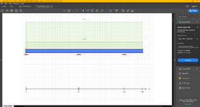
The attached report shows the points of +,- moment etc.
1747936642214.png
 

Attachments

Last edited:
Hello,

Could someone here help me understand the process of using NDS TR14 and how to apply it to the attached beam.

I don't think I understand the process. Do I look at this as 3 separate spans and find the maximum moment inside of each span as well as the quarter moments in each span for use in calculating Cb? If so, is the purpose of this to determine the controlling span for unbraced length? And then I use that Cb for all spans since it is the same beam?

Could someone here give me a understanding of how to approach this.

Another thing that confuses me is, this beam has inflection points so different portions of the beam will have top flange in compressions and sections will have the bottom flange in compression.

I guess I'm confused on how to break it all down for analysis.-- The loads probably don't require this level of detail but I would still like to know the approach for the future.

In my instance, this is a double 2x12 beam that has 2x10 joist framing into the side of it with joist hangers. The reaction points shown are actually 6x6 post. Decking is attached to the top edge of the beam.

The attached report shows the points of +,- moment etc.
The analysis is of a continuous beam 13' long, consisting of two spans and one cantilever. Loading is 0.07+0.28 k/' labeled LL (perhaps that should be DL+LL).
I don't know what you mean by Cb and I don't know why you are concerned about unbraced length because the 3x12 beam is laterally braced by 2x10 joists supported with joist hangers, so I would assume the unbraced length is the spacing of the joists, which means it is not a factor in design.

The shear force, bending moment and deflection diagrams are based on the specified loading over the full length of beam, without considering the possibility of some spans unloaded. Moments and deflections in the second span would be much larger if the first span and cantilever were unloaded.

A thorough analysis would require consideration of skip loading, but it would be unusual to use such an analysis for such small spans and loads. Most engineers, I expect, would use coefficients or approximate hand methods.
 
Last edited:
The analysis is of a continuous beam 13' long, consisting of two spans and one cantilever. Loading is 0.07+0.28 k/' labeled LL (perhaps that should be DL+LL).
I don't know what you mean by Cb and I don't know why you are concerned about unbraced length because the 3x12 beam is laterally braced by 2x10 joists supported with joist hangers, so I would assume the unbraced length is the spacing of the joists, which means it is not a factor in design.

The shear force, bending moment and deflection diagrams are based on the specified loading over the full length of beam, without considering the possibility of some spans unloaded. Moments and deflections in the second span would be much larger if the first span and cantilever were unloaded.

A thorough analysis would require consideration of skip loading, but it would be unusual to use such an analysis for such small spans and loads. Most engineers, I expect, would use approximate hand methods.
Thank you for your response here BAretired

Thank you also for the idea about the pattern/ skip loading. I hadn't really thought about that where I was so focused on understanding this one concept. I will put that in my model so I can see the results. I follow you on the hand methods, I just wanted to see what a new software I've gotten ahold of can do so I will move forward with the pattern loading as you specified.-- agree that it really isn't necessary in this instance though.

Yes, I agree with your explanation of the beam and loading. I do agree with the unbraced length of the beam being the distance between joist.

Cb is a term from AISC, Cb is a bending modification factor that accounts for the variation of the bending moment along the unbraced length of a structural member, typically a beam.

In the publication, they also give another way to calculate the Cl or the beam stability factor so that it will also coincide nicely with NDS code.

Essentially NDS published TR14 to give guidance for the below shortfall of the NDS code. (Their guidance follows closely with what AISC had already done in previous work)

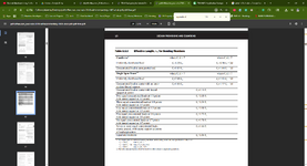
NDS table 3.3.3 is effective length formulas for bending- only holds true for very limited applications of simple span and cantilever conditions. It doesn't work for any continuous span beams and this is the reason for publication of TR14 (previously attached)

I found a good video on youtube (linked below)that if I can ever understand it completely, I think will give good understanding of this.
The whole video is an overview of what I'm trying to understand and apply for NDS but at minute 27 he is in the deep end and working through an example of what I am trying to apply to this beam.

Cb Lateral Torsional Buckling AISC Video- Youtube

1748017418165.png

1748015269981.png
 
Thank you for your response here BAretired

Thank you also for the idea about the pattern/ skip loading. I hadn't really thought about that where I was so focused on understanding this one concept. I will put that in my model so I can see the results. I follow you on the hand methods, I just wanted to see what a new software I've gotten ahold of can do so I will move forward with the pattern loading as you specified.-- agree that it really isn't necessary in this instance though.

Yes, I agree with your explanation of the beam and loading. I do agree with the unbraced length of the beam being the distance between joist.

Cb is a term from AISC, Cb is a bending modification factor that accounts for the variation of the bending moment along the unbraced length of a structural member, typically a beam.

In the publication, they also give another way to calculate the Cl or the beam stability factor so that it will also coincide nicely with NDS code.

Essentially NDS published TR14 to give guidance for the below shortfall of the NDS code. (Their guidance follows closely with what AISC had already done in previous work)

NDS table 3.3.3 is effective length formulas for bending- only holds true for very limited applications of simple span and cantilever conditions. It doesn't work for any continuous span beams and this is the reason for publication of TR14 (previously attached)

I found a good video on youtube (linked below)that if I can ever understand it completely, I think will give good understanding of this.
The whole video is an overview of what I'm trying to understand and apply for NDS but at minute 27 he is in the deep end and working through an example of what I am trying to apply to this beam.

Cb Lateral Torsional Buckling AISC Video- Youtube

View attachment 9897

View attachment 9896
There is a lot of information in NDS TR14. When I think of all the timber beams I have designed over a fifty four year period and never thought about Lateral Torsional Buckling, it makes me cringe.

Continuous spans with dimension lumber is usually not much of a problem because they are usually braced by joists (but not always).

I am not familiar with the methods described in NDS TR14; it would take some time to learn them. Sorry I can't be more helpful at this time, but at 92, my synapses are further and further apart.
I follow you on the LTB comment.

When I took my research on all of this to the end. I ended up following the gist of what you had said from your experience.

Essentially with the joist framing into the beam on such short intervals (16" or 12" depending on the situation). And with lateral support at both the top and bottom since the beam was continuous. The CL factor (beam stability) defaults to 1. So it doesn't modify the allowable for bending outside of the other factors such as Cd etc. (duration factor).

Due to this, luckily, I didn't have to go into the information within TR14 any deeper than just knowing it is out there if needed.
 
Last edited:

Part and Inventory Search

Sponsor

Back
Top